background image

10.2.2 

Mounting Procedure

If the gearbox and motor have been checked on their quality, the following

assembly procedure is recommended.

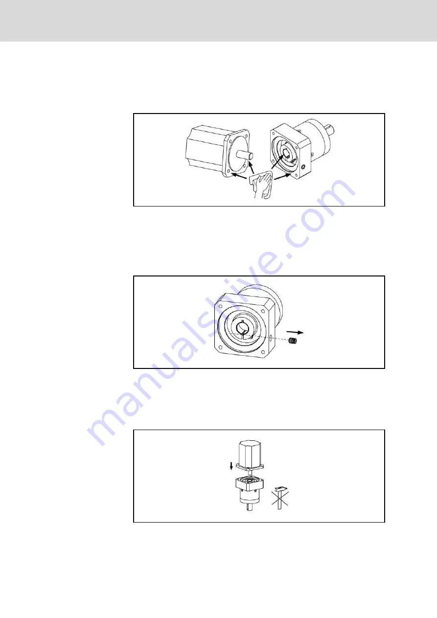
1. Clean and check the parts.

Fig.10-1:

Cleaning of the parts before mounting

Check  for  damage  to  the  motor  shaft,  compression  coupling  bore  and

any  bushing,  as  well  as  the  faces  of  motor  and  gearbox  flanges  and

clean  them  free  from  grease  thoroughly.  Do  not  clean  the  parts  with

compressed air. Avoid using aggressive detergents, which could dam‐

age the seals.

2. Remove cap screws.

Fig.10-2:

Remove the cover screws

Remove  the  cover  screws  from  the  gearbox  connection  flange,  which

covers  the  access  to  the  clamping  screw.  Turn  the  compression  cou‐

pling so that the heads of the clamping screws line up with the tapped

holes, which have now been opened in the gearbox`s adapter plate.

3. Insert the motor shaft into the gearbox

Fig.10-3:

Insert the motor shaft into the gearbox

Insert the motor shaft into the gearbox coupling until the gearbox´s con‐

necting flange and the motor face are fully in contact. It `should be pos‐

Bosch Rexroth AG

 DOK-GEAR**-GTE********-PR08-EN-P

 Rexroth GTE Planetary Gearboxes

68/83

Assembly

Содержание GTE Series

Страница 1: ...Project Planning Manual Electric Drives and Controls Pneumatics Service Linear Motion and Assembly Technologies Hydraulics Rexroth GTE Planetary Gearboxes R911308842 Edition 08 ...

Страница 2: ...ation set forth in it are the exclusive property of Bosch Rexroth AG It may not be re produced or given to third parties without its consent Liability The specified data is intended for product description purposes only and shall not be deemed to be a guaranteed characteristic unless expressly stipulated in the contract All rights are reserved with respect to the content of this docu mentation and...

Страница 3: ...n Against Electric Shock 15 3 3 3 Protection Against Dangerous Movements 16 3 3 4 Protection Against Magnetic and Electromagnetic Fields During Operation and Mounting 17 3 3 5 Protection Against Contact With Hot Parts 18 3 3 6 Protection During Handling and Mounting 18 3 3 7 Battery Safety 18 3 3 8 Protection Against Pressurized Systems 19 3 4 Explanation of Signal Words and the Safety Alert Symbo...

Страница 4: ... 5 6 GTE160 44 6 6 Permitted Shaft Load 45 6 6 1 General 45 6 6 2 GTE040 46 6 6 3 GTE060 47 6 6 4 GTE080 48 6 6 5 GTE120 49 6 6 6 GTE160 50 7 Specifications 51 7 1 GTE040 51 7 2 GTE060 52 7 3 GTE080 53 7 4 GTE120 54 7 5 GTE160 55 8 Type Codes 57 8 1 Notes on Connecting a Motor acc to ATEX Standard 57 8 2 Type Code GTE040 58 8 3 Type Code GTE060 59 8 4 Type Code GTE080 60 8 5 Type Code GTE120 61 8 ...

Страница 5: ...al Information 72 11 4 2 Measures 73 11 5 Troubleshooting 73 11 5 1 General Information 73 11 5 2 Excess Temperature of Gearbox Housing 73 11 5 3 Gearbox Motor Unit Generates Vibrations 74 11 5 4 Specified Position is not Attained 74 12 Ordering Designations 75 12 1 General Information 75 12 2 Notes on Connecting a Motor acc to ATEX Standard 75 13 Environmental Protection and Disposal 77 13 1 Envi...

Страница 6: ...Bosch Rexroth AG DOK GEAR GTE PR08 EN P Rexroth GTE Planetary Gearboxes IV 83 ...

Страница 7: ...rious sectors of indus try They are well suited for use with gear racks or toothed belts in handling sys tems with high speed and accelerations e g loader and robots The low backlash with shave grinded honed planet wheels permits the exe cution of exact positioning tasks Furthermore the gearboxes are suited for S1 operation required for application in e g the printing sector DOK GEAR GTE PR08 EN P...

Страница 8: ...hrough lifetime lubrication Use under adverse environmental conditions is possible due to the com pletely enclosed IP54 design Safe and lasting sealing by abradant bearing sealants Hermetically sealed housing Non positive from backlash free torque transmission via the compres sion coupling High performance data High accuracy via shave grinded honed planetary wheels low back lash gearing with low t...

Страница 9: ... subdivided into the following focal points Chapter Title Content 1 Introduction to the Product General Information 2 Important Instructions on Use Safety 3 Safety Instructions 4 Dimensioning and Selection Product Description for planners and designers 5 Application Notes 6 Technical Data 7 Specifications 8 Type Codes 9 Handling Transport and Storage Practise for operating and maintenance personne...

Страница 10: ...our experiences are an essential part of the process of improving both the product and the documentation Please do not hesitate to inform us of any error you detect in this documenta tion or of any modifications you might desire We would appreciate your feed back Please send your remarks to Bosch Rexroth AG Dept DC IA EDM3 jw mb Buergermeister Dr Nebel Strasse 2 97816 Lohr am Main Germany Email do...

Страница 11: ... Software products must not be decompiled their source codes must not be modified Damaged or improperly working products must not be installed or put in to operation It must be ensured that the products are installed according to the regu lations specified in the documentation 2 1 2 Areas of Use and Application Typical application ranges of the GTE planetary gearboxes are Handling and Mounting sys...

Страница 12: ...specified in this documentation is considered as non intended use Planetary gearboxes may not be used if They are subject to operating conditions which do not comply with the ambient conditions described above E g operation under water under extreme variations in temperature or extreme maximum temperatures is not permitted the intended application is not explicitly released by Bosch Rexroth Please...

Страница 13: ...onding lines and ca bles Installation An installation consists of several devices or systems interconnected for a defined purpose and on a defined site which however are not intended to be placed on the market as a single functional unit Machine A machine is the entirety of interconnected parts or units at least one of which is movable Thus a machine consists of the appropriate machine drive eleme...

Страница 14: ...njury electric shock or even death 3 2 2 Requirements for Safe Use Read the following instructions before initial commissioning of the compo nents of the electric drive and control system in order to eliminate the risk of injury and or property damage You must follow these safety instructions Rexroth is not liable for damages resulting from failure to observe the safety instructions Read the opera...

Страница 15: ...EMC in the respective application docu mentation The machine or installation manufacturer is responsible for compliance with the limit values as prescribed in the national regulations The technical data connection and installation conditions of the compo nents are specified in the respective application documentations and must be followed at all times National regulations which the user must take ...

Страница 16: ...o all electric components in accordance with the connection diagram Even for brief measurements or tests operation is only allowed if the equipment grounding conductor has been permanently connected to the points of the components provided for this purpose Before accessing electrical parts with voltage potentials higher than 50 V you must disconnect electric components from the mains or from the p...

Страница 17: ...s section outer con ductor Minimum cross section equipment grounding conductor Leakage current 3 5 mA 1 equipment grounding conductor 2 equipment grounding conductors 1 5 mm2 AWG 16 10 mm2 AWG 8 2 1 5 mm2 AWG 16 2 5 mm2 AWG 14 2 2 5 mm2 AWG 14 4 mm2 AWG 12 2 4 mm2 AWG 12 6 mm2 AWG 10 2 6 mm2 AWG 10 10 mm2 AWG 8 16 mm2 AWG 6 16 mm2 AWG 6 25 mm2 AWG 4 35 mm2 AWG 2 50 mm2 AWG 1 0 25 mm2 AWG 4 70 mm2 ...

Страница 18: ...y drive movements will occur The extent of faulty drive movements depends upon the type of control and the state of opera tion Dangerous movements Danger to life risk of injury serious injury or property damage A risk assessment must be prepared for the installation or machine with its specific conditions in which the components of the electric drive and control system are installed As a result of...

Страница 19: ...he electric drive and control system for possible malfunctions when operating such high fre quency remote control and radio equipment in its possible positions of normal use It might possibly be necessary to perform a special electro magnetic compatibility EMC test 3 3 4 Protection Against Magnetic and Electromagnetic Fields During Oper ation and Mounting Magnetic and electromagnetic fields genera...

Страница 20: ...the machine or in stallation guards shieldings or barriers or safety instructions in the ap plication documentation 3 3 6 Protection During Handling and Mounting Risk of injury by improper handling Injury by crushing shearing cutting hit ting Observe the relevant statutory regulations of accident prevention Use suitable equipment for mounting and transport Avoid jamming and crushing by appropriate...

Страница 21: ...ructions Before dismounting lines relieve pressure and empty medium Use suitable protective equipment safety goggles safety shoes safety gloves for example Immediately clean up any spilled liquids from the floor due to the risk of falling Environmental protection and disposal The agents e g fluids used to operate the product might not be environmentally friendly Dispose of agents harmful to the en...

Страница 22: ... case of non compliance with this safety instruction minor or moderate in jury could occur NOTICE In case of non compliance with this safety instruction property damage could occur Bosch Rexroth AG DOK GEAR GTE PR08 EN P Rexroth GTE Planetary Gearboxes 20 83 Safety Instructions for Electric Drives and Controls ...

Страница 23: ...n is mainly made according to the necessa ry maximum torque Mmax and the average velocity Vaverage resp mean speed naverage Continuous operation with pause interval This operation is characteristic for all highly dynamic feeds These are often found in winding machines drive rolls and in portioning devices in the sheet metal paper plastic and packaging industry Fig 4 2 Speed time diagram for operat...

Страница 24: ...device is to be taking in the following into consideration Frictional torque Starting torque Processing torque Accelerating torque Effective speed Necessary speed ON time Dimensioning criteria The motor gearbox combination must fulfill the following conditions The necessary speed must be reached The continuous torque rating of the motor gearbox combination has to be higher than the effective load ...

Страница 25: ...cycle rates are necessary the GTM gearbox must be derated accordingly see Fig 5 3 It must be ensured that the maximum motor torque is smaller than the maximum gearbox input torque the maximum motor speed is smaller than the maximum per missible gearbox input speed DOK GEAR GTE PR08 EN P Rexroth GTE Planetary Gearboxes Bosch Rexroth AG 23 83 Dimensioning and Selection ...

Страница 26: ...Bosch Rexroth AG DOK GEAR GTE PR08 EN P Rexroth GTE Planetary Gearboxes 24 83 ...

Страница 27: ...g against contact of parts under load or moving parts Penetration of firm foreign bodies and water At motors and the mounted servo gearboxes GTE the following protection class IP 54 is valid for the housing of motor and gearbox for the output shaft of the gearbox for the power and encoder connection on the motor at professional mounting The first reference number defines the degree of protection a...

Страница 28: ... up to 1 000 cycles per hour Are more than 1 000 cycles per hour during operation of the gearbox neces sary the technical data have to be reduced by a factor see Fig 5 3 Fig 5 3 Operating mode S5 intermittent duty with electronical braking Reduction at Higher Cycles Are higher cycles than 1 000 cycles per hour needed the following reduced technical data regarding torque and power are valid Fig 5 4...

Страница 29: ... of construction installation position Rexroth planetary gearboxes GTE are manufactured in the construction B05 for flange mounting The installation positions can be done as described in the following table according to EN 60034 7 1996 06 Gearbox Type of construc tion Permissible installation positions according to EN 60034 7 1996 06 Important Installation Note B05 Vertical mounting position IM V3...

Страница 30: ...ime were 30 000 operation hours taken as basis bearing calcula tion according to DIN ISO 281 1993 01 The axial shaft load is also described in the chapter 6 2 Permittable Shaft Load Assembly of output elements The output shaft of the GTE gearboxes is fitted with a massive shaft shoul der which is well suited for the support of axial forces especially at key con nections The according tightening to...

Страница 31: ...le motor gearbox combination with GTE planetary gearboxes Planetary gear Motor type MSM MSK KSM GTE040 MSM019A MSM019B MSM020B Not possible Not possible GTE060 MSM030B MSM031B MSK030 Not possible GTE080 MSM030C MSM031C MSM040B MSM041B MSK030 MSK040 KSM041 GTE120 MSM040B MSM041B MSK040 MSK050 MSK060 MSK061 KSM041 KSM061 GTE160 Not possible MSK050 MSK060 MSK061 MSK070 MSK071 MSK075 MSK076 MSK100 KSM...

Страница 32: ...Bosch Rexroth AG DOK GEAR GTE PR08 EN P Rexroth GTE Planetary Gearboxes 30 83 ...

Страница 33: ...5 96 96 94 Moment of inertia 11 J kgcm 0 031 0 022 0 019 0 017 0 016 0 029 0 019 0 016 Mass m kg 0 35 0 35 0 35 0 35 0 35 0 45 0 45 0 45 Lifetime LH 30 000 Lubrication Life lubrication Ambient temperature Tamb C 0 40 Gearbox housing temperature 2 TG C 25 90 Sound pressure level 3 LP dB A 58 Degree of protection IP54 1 these values refer to a speed of the output shaft of nout 100 min 1 on duty cycl...

Страница 34: ... 11 J kgcm 0 135 0 093 0 078 0 065 0 064 0 127 0 075 0 064 Mass m kg 0 9 0 9 0 9 0 9 0 9 1 1 1 1 1 1 Lifetime LH 30 000 Lubrication Life lubrication Ambient temperature Tamb C 0 40 Gearbox housing temperature 2 TG C 25 90 Sound pressure level 3 LP dB A 58 Degree of protection IP54 1 these values refer to a speed of the output shaft of nout 100 min 1 on duty cycle KA 1 and S1 mode for electrical ma...

Страница 35: ...J kgcm 0 77 0 52 0 45 0 39 0 39 0 72 0 44 0 39 Mass m kg 2 1 2 1 2 1 2 1 2 1 2 6 2 6 2 6 Lifetime LH 30 000 Lubrication Life lubrication Ambient temperature Tamb C 0 40 Gearbox housing temperature 2 TG C 25 90 Sound pressure level 3 LP dB A 60 Degree of protection IP54 1 these values refer to a speed of the output shaft of nout 100 min 1 on duty cycle KA 1 and S1 mode for electrical machines and T...

Страница 36: ... of inertia 11 J kgcm 2 63 1 79 1 53 1 32 1 3 2 56 1 5 1 3 Mass m kg 6 6 6 6 6 8 8 8 Lifetime LH 30 000 Lubrication Life lubrication Ambient temperature Tamb C 0 40 Gearbox housing temperature 2 TG C 25 90 Sound pressure level 3 LP dB A 65 Degree of protection IP54 1 these values refer to a speed of the output shaft of nout 100 min 1 on duty cycle KA 1 and S1 mode for electrical machines and T 30 ...

Страница 37: ... 12 14 7 78 6 07 4 63 12 37 6 65 5 28 Mass m kg 18 18 18 18 22 22 22 Lifetime LH 30 000 Lubrication Life lubrication Ambient temperature Tamb C 0 40 Gearbox housing temperature 2 TG C 25 90 Sound pressure level 3 LP dB A 70 Degree of protection IP54 1 these values refer to a speed of the output shaft of nout 100 min 1 on duty cycle KA 1 and S1 mode for electrical machines and T 30 C 2 referring to...

Страница 38: ...ic T2N T2max Fig 6 6 Increase facture depending on the number of rotations of the output shaft The maximum application torque must not exceed 1 6 x Mout nenn The num ber of rotations of the output shaft at the max torque has to be calculated If the number of rotations is larger than 15 000 000 the gearbox may only be subjected to the nominal torque of the gearbox If the number of rotations is smal...

Страница 39: ...late connection on machine bed one sided 30 C In the case of a required output torque of 100 Is nm smaller than the nominal initial speed at 100 load the gearbox is thermally suitable In the case of a required output torque of 50 Is nm smaller than the nominal initial speed at 50 load the gearbox is thermally suit able If conditions are unfavorable please reduce the speeds or consult Bosch Rexroth...

Страница 40: ... of more than 20 000h is required the technical data re garding torque and speed have to be reduced by the following diagram Fig 6 7 Reduction of the technical data for increased lifetime The permitted technical operating data may not be exceeded Bosch Rexroth AG DOK GEAR GTE PR08 EN P Rexroth GTE Planetary Gearboxes 38 83 Technical Data ...

Страница 41: ...e am bient temperature is higher than 30 C The determined limiting characteristic curves are related on an ambient temperature of 30 C at unhindered air circulation and fastening on the steel flange which is more than twice as wide as the gearbox and has a temperature of 30 C Overload of the gearbox due to exceeding the permitted gearbox housing temperature of 90 C NOTICE During operation of motor...

Страница 42: ...0 limiting temperature curves at ΔT 60K Mout Output torque nin Input speed Fig 6 8 Ratio at limiting temperature curves GTE040 Bosch Rexroth AG DOK GEAR GTE PR08 EN P Rexroth GTE Planetary Gearboxes 40 83 Technical Data ...

Страница 43: ...0 limiting temperature curves at ΔT 60K Mout Output torque nin Input speed Fig 6 9 Ratio at limiting temperature curves GTE060 DOK GEAR GTE PR08 EN P Rexroth GTE Planetary Gearboxes Bosch Rexroth AG 41 83 Technical Data ...

Страница 44: ...0 limiting temperature curves at ΔT 60K Mout Output torque nin Input speed Fig 6 10 Ratio at limiting temperature curves GTE080 Bosch Rexroth AG DOK GEAR GTE PR08 EN P Rexroth GTE Planetary Gearboxes 42 83 Technical Data ...

Страница 45: ...0 limiting temperature curves at ΔT 60K Mout Output torque nin Input speed Fig 6 11 Ratio at limiting temperature curves GTE120 DOK GEAR GTE PR08 EN P Rexroth GTE Planetary Gearboxes Bosch Rexroth AG 43 83 Technical Data ...

Страница 46: ...0 limiting temperature curves at ΔT 60K Mout Output torque nin Input speed Fig 6 12 Ratio at limiting temperature curves GTE160 Bosch Rexroth AG DOK GEAR GTE PR08 EN P Rexroth GTE Planetary Gearboxes 44 83 Technical Data ...

Страница 47: ...peed of the cycle Fig 6 13 Permitted shaft load of GTE gearboxes Basis of design The GTE gearboxes are designed for a L10h bearing life of 30 000 hours For radial forces FRerf which lie over the value of the diagram decreases the nominal bearing lifetime as follows FR permittable radial force FRerf necessary radial force DOK GEAR GTE PR08 EN P Rexroth GTE Planetary Gearboxes Bosch Rexroth AG 45 83...

Страница 48: ...040 Permitted axial force FA 160N FA permittable axial force FR permittable radial force Do occur higher axial forces the bearing lifetime for this use has to be calcu lated individually Bosch Rexroth AG DOK GEAR GTE PR08 EN P Rexroth GTE Planetary Gearboxes 46 83 Technical Data ...

Страница 49: ...060 Permitted axial force FA 450N FA permittable axial force FR permittable radial force Do occur higher axial forces the bearing lifetime for this use has to be calcu lated individually DOK GEAR GTE PR08 EN P Rexroth GTE Planetary Gearboxes Bosch Rexroth AG 47 83 Technical Data ...

Страница 50: ...080 Permitted axial force FA 900N FA permittable axial force FR permittable radial force Do occur higher axial forces the bearing lifetime for this use has to be calcu lated individually Bosch Rexroth AG DOK GEAR GTE PR08 EN P Rexroth GTE Planetary Gearboxes 48 83 Technical Data ...

Страница 51: ...20 Permitted axial force FA 2 100N FA permittable axial force FR permittable radial force Do occur higher axial forces the bearing lifetime for this use has to be calcu lated individually DOK GEAR GTE PR08 EN P Rexroth GTE Planetary Gearboxes Bosch Rexroth AG 49 83 Technical Data ...

Страница 52: ...60 Permitted axial force FA 6 000N FA permittable axial force FR permittable radial force Do occur higher axial forces the bearing lifetime for this use has to be calcu lated individually Bosch Rexroth AG DOK GEAR GTE PR08 EN P Rexroth GTE Planetary Gearboxes 50 83 Technical Data ...

Страница 53: ...ype One stage Two stage K1 L B L B mm mm mm mm mm MSM020B 93 5 28 5 106 5 28 5 40 MSM019A B 93 5 28 5 106 5 28 5 40 1 biggest flange size motor gearbox Tab 7 2 Dimensional details GTE040 one and two stage DOK GEAR GTE PR08 EN P Rexroth GTE Planetary Gearboxes Bosch Rexroth AG 51 83 Specifications ...

Страница 54: ...ge K1 L B L B mm mm mm mm mm MSK030 106 24 5 118 5 24 5 60 MSM030B 113 31 2 125 5 31 2 60 MSM031B 113 31 2 125 5 31 2 60 1 biggest flange size motor gearbox Tab 7 4 Dimensional details GTE060 one and two stage Bosch Rexroth AG DOK GEAR GTE PR08 EN P Rexroth GTE Planetary Gearboxes 52 83 Specifications ...

Страница 55: ... MSK040 134 33 5 151 33 5 90 MSM030C 134 33 5 151 33 5 80 MSM031C 134 33 5 151 33 5 80 MSM040B 138 5 38 5 156 38 5 90 MSM041B 138 5 38 5 156 38 5 90 KSM041 134 33 5 151 33 5 90 1 biggest flange size motor gearbox Tab 7 6 Dimensional details GTE080 one and two stage DOK GEAR GTE PR08 EN P Rexroth GTE Planetary Gearboxes Bosch Rexroth AG 53 83 Specifications ...

Страница 56: ...6 5 47 5 203 5 47 5 115 MSK060 186 5 57 5 115 MSK061 176 5 47 5 115 MSM040B 176 5 47 5 203 5 47 5 115 MSM041B 176 5 47 5 203 5 47 5 115 KSM041 176 5 47 5 203 5 47 5 115 KSM061 176 5 47 5 115 1 biggest flange size motor gearbox Tab 7 8 Dimensional details GTE120 one and two stage Bosch Rexroth AG DOK GEAR GTE PR08 EN P Rexroth GTE Planetary Gearboxes 54 83 Specifications ...

Страница 57: ... MSK070 263 5 72 5 313 72 5 140 MSK071 263 5 72 5 313 72 5 140 MSK075 263 5 72 5 313 72 5 140 MSK076 255 5 64 5 305 64 5 140 MSK100 265 5 74 5 190 KSM061 255 5 64 5 305 64 5 140 KSM071 263 5 72 5 313 72 5 140 KSM076 255 5 64 5 305 64 5 140 1 biggest flange size motor gearbox Tab 7 10 Dimensional details GTE160 one and two stage DOK GEAR GTE PR08 EN P Rexroth GTE Planetary Gearboxes Bosch Rexroth A...

Страница 58: ...Bosch Rexroth AG DOK GEAR GTE PR08 EN P Rexroth GTE Planetary Gearboxes 56 83 ...

Страница 59: ...n Ex mo tors like MSK motors acc to ATEX Standard are no products of Rexroth and will not be offered or delivered neither separately nor mounted Basically assembly of ATEX gearboxes onto Rexroth motors is possible The gearboxes have to be directly ordered at the supplier and mounted by your self for manufacturer recommendation refer to chapter 5 2 Use of gearbox es or motor gearbox combinations in...

Страница 60: ...4 4 1 004 One stage 5 5 1 005 One stage 8 8 1 008 One stage 10 10 1 010 Two stage 12 12 1 012 Two stage 20 20 1 020 Two stage 40 40 1 040 with key A Plain B 0 1 2 3 1 2 3 4 5 6 7 8 9 0 1 2 3 4 5 6 7 8 9 0 1 2 3 4 5 6 7 8 9 0 Example G T E 0 4 0 N N 1 0 0 4 A N N 4 1 ZN40019 060 2012 11 12 Size Product 019A B 020B MSM N 45 N N 41 N Fig 8 1 Type Code GTE040 Bosch Rexroth AG DOK GEAR GTE PR08 EN P Re...

Страница 61: ...e stage 5 5 1 005 One stage 8 8 1 008 One stage 10 10 1 010 Two stage 12 12 1 012 Two stage 20 20 1 020 Two stage 40 40 1 040 with key A Plain B 0 1 2 3 1 2 3 4 5 6 7 8 9 0 1 2 3 4 5 6 7 8 9 0 1 2 3 4 5 6 7 8 9 0 Example G T E 0 6 0 N N 1 0 0 4 A N N 4 2 ZN40019 060 2012 11 12 Size Product 025 030 030B 031B MKD NN02 MSK NN02 MSM N 42 N N 42 N Fig 8 2 Type code GTE060 DOK GEAR GTE PR08 EN P Rexroth...

Страница 62: ...ge 8 8 1 008 One stage 10 10 1 010 Two stage 12 12 1 012 Two stage 20 20 1 020 Two stage 40 40 1 040 with key A Plain B 0 1 2 3 1 2 3 4 5 6 7 8 9 0 1 2 3 4 5 6 7 8 9 0 1 2 3 4 5 6 7 8 9 0 Example G T E 0 8 0 N N 1 0 0 4 A N N 0 3 ZN40019 080 2012 11 12 Size Product 030 030C 031C 040 040B 041 041B 043C KSM N 03 N MSK N 02 N N 03 N N 03 N MSM N 43 N N 43 N N 44 N N 44 N Fig 8 3 Type code GTE080 Bosc...

Страница 63: ...0 1 010 Two stage 12 12 1 012 Two stage 20 20 1 020 Two stage 40 40 1 040 with key A Plain B 1 Only available with one stage gearbox Comment 0 1 2 3 1 2 3 4 5 6 7 8 9 0 1 2 3 4 5 6 7 8 9 0 1 2 3 4 5 6 7 8 9 0 Example G T E 1 2 0 N N 1 0 0 4 A N N 0 3 ZN40019 120 12 11 12 Size Product 040 040B 041 041B 043C 050 060 061 KSM N 03 N N 05 N 1 MSK N 03 N N 03 N N 20 N NN211 N 05 N 1 MSM N 44 N N 44 N Fi...

Страница 64: ... 12 1 012 Two stage 20 20 1 020 Two stage 40 40 1 040 With key der A Plain B Comment 1 Only available with one stage gearbox 0 1 2 3 1 2 3 4 5 6 7 8 9 0 1 2 3 4 5 6 7 8 9 0 1 2 3 4 5 6 7 8 9 0 Example G T E 1 6 0 N N 1 0 0 4 A N N 2 1 ZN40019 160 2007 05 11 Size Product 050 060 061 070 071 075 076 090 100 112 KSM NN05 NN16 NN06 MKD NN05 NN06 NN091 MSK NN20 NN21 NN05 NN16 NN16 NN16 NN06 NN091 Fig 8...

Страница 65: ...code to im prove the read in via barcode scanner and to have an additional possibility to read in 1 2D Barcode 2 Barcode Fig 9 1 Name plate example GTE gearbox Motor Gearbox Combination The motor is delivered with its own separate type plate This is attached to the motor housing In addition a second type plate is attached using two side tape onto the original motor name plate The second type plate...

Страница 66: ...oid direct insolation UV light and ozone because it leads to deterioration of the sealants We recommend using a FIFO system First in first out Remove all the anticorrosive on the gearboxes before mounting them The GTE gearboxes are filled for life with lubrication and are ready for use The input and output are treated with anticorrosive coating Do not proceed cleaning via air pressure NOTICE The d...

Страница 67: ... transport For a long term storage please keep a tem perature range of 0 C to 30 C Store motors in dry places which are free from dust and vibrations Store motors horizontally Do not remove the plastic protective sleeve on the output shaft It pro tects the shaft from moisture rust and mechanical damage DOK GEAR GTE PR08 EN P Rexroth GTE Planetary Gearboxes Bosch Rexroth AG 65 83 Handling Transport...

Страница 68: ...Bosch Rexroth AG DOK GEAR GTE PR08 EN P Rexroth GTE Planetary Gearboxes 66 83 ...

Страница 69: ...r to compensate for the difference in diameter compared to the gear box clamping hub The clamping connection of the GTE gearboxes present an in novation which makes a high exactness at assembly possible The tension results from several closed slots whereby a precise cylindrical clamping can be reached The position of clamping ring bush and motor shaft is irrelevant for assembly Before mounting the...

Страница 70: ...could dam age the seals 2 Remove cap screws Fig 10 2 Remove the cover screws Remove the cover screws from the gearbox connection flange which covers the access to the clamping screw Turn the compression cou pling so that the heads of the clamping screws line up with the tapped holes which have now been opened in the gearbox s adapter plate 3 Insert the motor shaft into the gearbox Fig 10 3 Insert ...

Страница 71: ...g and or gearbox due to bracing during mount ing NOTICE Do the assembly process in vertical position 4 Connect the motor to the gearbox Fig 10 4 Tighten the motor fastening screws crossed Use screws with property class 8 8 The screws must be locked The screws must be tightened crossed with the respectively correct torque according to DIN to assure a proper connection of the gearbox with the motor ...

Страница 72: ...ide Gearbox type Pilot diameter Bolt size ISO grade Tightening torque mm Nm GTE040 26 M4 12 9 5 3 GTE060 40 M5 12 9 10 4 GTE080 60 M6 12 9 18 GTE120 80 M10 12 9 87 GTE160 130 M12 12 9 150 Tab 10 7 Flange mounting data for installing the gearbox on the machine Assure a non distorted mount when installing the gearbox Attachments part like gears or tooth lock washers have to be mounted on the output ...

Страница 73: ...are met proceed as follows 1 Commission the motors controllers and power supplies according to the corresponding descriptions Note the respective product documentation 2 Before releasing the setpoint check whether the set relationship of the maximum motor speed and the preset setpoint corresponds to the spec ifications for the machine 3 At a low turning speed check whether the rotation direction o...

Страница 74: ...ents DANGER Do not work on unsecured and operating machines Secure the machine against accidental movements and against unau thorized operation Before dismantling secure the gearbox motor unit and supply cables against falling or movements before disconnecting the mechanical con nections 1 Observe the instructions of the machine documentation 2 Please heed the safety notes and carry out all steps ...

Страница 75: ... operating hours Remove dust chips and other dirt from the gearbox motor housing cooling fins and the connections Depending on the degree of soiling but after 6 month operation at the latest Do it monthly at strong pollution Tab 11 1 Gearbox motor unit maintenance plan 11 5 Troubleshooting 11 5 1 General Information Danger of injury due to moving elements Danger of injury due to hot surfaces WARNI...

Страница 76: ... the gearbox for damage In the case of loss contact Rexroth Service 3 Fasten motor properly and check for damage In the case of loss con tact Rexroth Service 4 Check parameters of the drive system motor and encoder data Ob serve the notes in the documentation for the drive controller 11 5 4 Specified Position is not Attained Status The positioning command of the control unit is not precisely execu...

Страница 77: ...TEX directive and combining a GTE planetary gearbox with an explosion proof motor e g MSK Motor acc to ATEX stand ard please contact your responsible sales office Servo planetary gearboxes acc to ATEX for mounting on Ex mo tors like MSK motors acc to ATEX Standard are no products of Rexroth and will not be offered or delivered neither separately nor mounted Basically assembly of ATEX gearboxes ont...

Страница 78: ...Bosch Rexroth AG DOK GEAR GTE PR08 EN P Rexroth GTE Planetary Gearboxes 76 83 ...

Страница 79: ...the products free domicile to the following address Bosch Rexroth AG Electric Drives and Controls Buergermeister Dr Nebel Strasse 2 97816 Lohr am Main Germany Packaging The packaging materials consist of cardboard wood and polystyrene These materials can be recycled anywhere without any problem For ecological reasons please refrain from returning the empty packages to us Batteries and Accumulators...

Страница 80: ...oducts made of plastics can contain flame retardants These plastic parts are labeled according to EN ISO 1043 They have to be recycled separately or disposed of according to the valid legal requirements Bosch Rexroth AG DOK GEAR GTE PR08 EN P Rexroth GTE Planetary Gearboxes 78 83 Environmental Protection and Disposal ...

Страница 81: ...ional information on service repair e g delivery addresses and training can be found on our internet sites Service worldwide Outside Germany please contact your local service office first For hotline numbers refer to the sales office addresses on the internet Preparing information To be able to help you more quickly and efficiently please have the following information ready Detailed description o...

Страница 82: ...Bosch Rexroth AG DOK GEAR GTE PR08 EN P Rexroth GTE Planetary Gearboxes 80 83 ...

Страница 83: ...s exclusion of liability 9 Installation positions 27 Intended use Introduction 9 Intermitted operation 26 L Limiting temperature curves 39 M Maintenance 72 Manufacturer for ATEX gearboxes 27 Maximum transferable output torque 36 Mechanical features 27 Mode of functioning 6 Motor Mounting 67 Mounting procedure 68 N Name plate 63 O Operating conditions 25 Operating mode 26 Operational reliability 6 ...

Страница 84: ...ous operation 31 Thermal specifications for S1 operation 37 Transport 64 Triangular operation with pause interval 21 Troubleshooting 73 Type Code GTE040 58 Type Code GTE060 59 Type Code GTE080 60 Type Code GTE120 61 Type Code GTE160 62 U Use 9 Bosch Rexroth AG DOK GEAR GTE PR08 EN P Rexroth GTE Planetary Gearboxes 82 83 Index ...

Страница 85: ...Notes DOK GEAR GTE PR08 EN P Rexroth GTE Planetary Gearboxes Bosch Rexroth AG 83 83 ...

Страница 86: ... GEAR GTE PR08 EN P Bosch Rexroth AG Electric Drives and Controls P O Box 13 57 97803 Lohr Germany Bgm Dr Nebel Str 2 97816 Lohr Germany Tel 49 9352 18 0 Fax 49 9352 18 8400 www boschrexroth com electrics ...

Отзывы: