


24
Intera 5.3
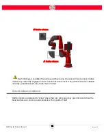
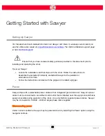
Getting Started with Sawyer
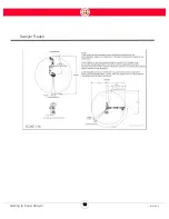
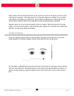
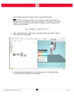
When homing, the joint limit indicators running vertically along the right side of the display appear.
When a joint is twisted effectively, its indicator turns green. Joints that are not yet twisted are gray.
Note:
You can also manually home the arm by physically moving each joint five degrees.
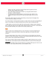
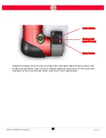
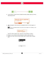
Moving the Arm
The robot has three physical interfaces used to manipulate the robot and train a task: two
Navigators and one training cuff.
One Navigator is located on Sawyer’s arm. The other is on the torso. A Navigator is a set of buttons
and a knob you use to make selections on Sawyer. The selections are shown on Sawyer’s display.
The training cuff is located at the end of Sawyer’s arm, between the wrist and end of arm tooling.
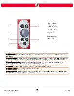
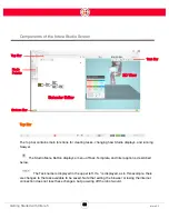
Grab anywhere along Sawyer’s arm and push and pull on it slightly to feel its resistance. Notice that
the arm is stiff yet compliant. Now, grab the indented portion of the training cuff above the buttons
and squeeze it. Notice that the arm becomes fluid and easy to manipulate. This is what we call
“Zero G” mode. It is the mode in which you train Sawyer to perform a task. While the arm is in Zero-
G mode, the motors are enabled, essentially counteracting the effect of gravity on the robot.
You can also press and hold the O button on the Navigator to enable Zero G mode.
Содержание Sawyer
Страница 15: ...8 Intera 5 3 Getting to Know Sawyer Hardware Overview of Your Robot ...
Страница 16: ...9 Intera 5 3 Getting to Know Sawyer Dimensions ...
Страница 17: ...10 Intera 5 3 Getting to Know Sawyer Sawyer Reach ...
Страница 21: ...14 Intera 5 3 Getting to Know Sawyer Bottom View Inputs Power Air Input Outputs 4x Air Power and Data Video ...
Страница 93: ...86 Intera 5 3 Train Pick and Place Patterns on the Head 11 Press OK to go to the next step ...
Страница 98: ...91 Intera 5 3 Train Pick and Place Patterns on the Head 16 Press OK to allow modifications to the direction ...
Страница 104: ...97 Intera 5 3 Train Pick and Place Patterns on the Head You may now run the task ...
Страница 134: ...127 Intera 5 3 TCP IP The Set To node in the Behavior Editor is used to output information ...
Страница 138: ...131 Intera 5 3 Fieldbus Devices 3 Using a keyboard navigate to CONFIGURATION and press ENTER ...
Страница 155: ...148 Intera 5 3 ...
Страница 156: ...149 Intera 5 3 ...
Страница 175: ...168 Intera 5 3 Figure D 8 Flow chart for determining when to use 1 Figure D 4 or 2 Figures D 6 and D 7 ...
Страница 180: ...173 Intera 5 3 ...
Страница 190: ...183 Intera 5 3 Fixed Data 112 From Robot ...
Страница 191: ...184 Intera 5 3 Standard Booleans 113 To Robot 114 From Robot Standard Integers 115 To Robot 116 From Robot ...
Страница 192: ...185 Intera 5 3 Standard Floats 117 To Robot 118 From Robot Small Booleans 119 To Robot 120 From Robot ...
Страница 193: ...186 Intera 5 3 Small Integers 121 To Robot 122 From Robot Small Floats 123 To Robot 124 From Robot ...
Страница 195: ...188 Intera 5 3 Large Floats 131 To Robot 132 From Robot Large Strings 133 To Robot 134 From Robot ...
Страница 206: ...199 Intera 5 3 Small Assembly 114 From Robot 115 To Robot ...
Страница 207: ...200 Intera 5 3 Large Assembly 116 From Robot 117 To Robot ...
Страница 208: ...201 Intera 5 3 Floats 118 From Robot 119 To Robot ...
Страница 209: ...202 Intera 5 3 Strings 120 From Robot 121 To Robot ...
Страница 218: ...Z Zero G button 16 17 Zero G mode 24 Zero Gravity mode 17 zoom reset 42 ...
Страница 219: ......
Страница 220: ...Last updated June 18 2018 Intera 5 3 User Guide Getting Started Rev A ...