


193
Intera 5.3
Appendix G2: Intera EtherNet/IP
Reference
For the latest and most detailed information on Sawyer and Intera 5, we always recommend you
see the Online User Guide at:
mfg.rethinkrobotics.com/intera.
The Rethink Robotics support page
is here:
Overview
The data tables in this document describe the format and byte addressing of the EtherNet/IP
Assemblies defined in the EDS (Electronic Data Sheet) for Intera. Multiple connection options are
available with the various Assemblies including a different mix of variable types and numbers, so
the best option can be chosen for each application.
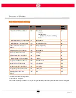
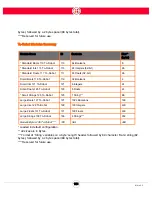
Default Connection - Standard Assemblies
The default EtherNet/IP connection defines a 'Standard To-Robot Assembly' and a 'Standard From-
Robot Assembly', each of which include a fixed number of general purpose variables of each data
type (Booleans, Integers, Floats, and Strings). For the Assembly sent from the robot, there are addi-
tional, automatically filled-in data fields related to the robot status, task status, and the state of the
safety signals. More information on these status fields can be found under the State Flags Defini-
tions section of this document.
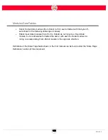
Setup Resources
The Rethink Intera EDS will be necessary to setup the Intera Adapter Device on the PLC.
Содержание Sawyer
Страница 15: ...8 Intera 5 3 Getting to Know Sawyer Hardware Overview of Your Robot ...
Страница 16: ...9 Intera 5 3 Getting to Know Sawyer Dimensions ...
Страница 17: ...10 Intera 5 3 Getting to Know Sawyer Sawyer Reach ...
Страница 21: ...14 Intera 5 3 Getting to Know Sawyer Bottom View Inputs Power Air Input Outputs 4x Air Power and Data Video ...
Страница 93: ...86 Intera 5 3 Train Pick and Place Patterns on the Head 11 Press OK to go to the next step ...
Страница 98: ...91 Intera 5 3 Train Pick and Place Patterns on the Head 16 Press OK to allow modifications to the direction ...
Страница 104: ...97 Intera 5 3 Train Pick and Place Patterns on the Head You may now run the task ...
Страница 134: ...127 Intera 5 3 TCP IP The Set To node in the Behavior Editor is used to output information ...
Страница 138: ...131 Intera 5 3 Fieldbus Devices 3 Using a keyboard navigate to CONFIGURATION and press ENTER ...
Страница 155: ...148 Intera 5 3 ...
Страница 156: ...149 Intera 5 3 ...
Страница 175: ...168 Intera 5 3 Figure D 8 Flow chart for determining when to use 1 Figure D 4 or 2 Figures D 6 and D 7 ...
Страница 180: ...173 Intera 5 3 ...
Страница 190: ...183 Intera 5 3 Fixed Data 112 From Robot ...
Страница 191: ...184 Intera 5 3 Standard Booleans 113 To Robot 114 From Robot Standard Integers 115 To Robot 116 From Robot ...
Страница 192: ...185 Intera 5 3 Standard Floats 117 To Robot 118 From Robot Small Booleans 119 To Robot 120 From Robot ...
Страница 193: ...186 Intera 5 3 Small Integers 121 To Robot 122 From Robot Small Floats 123 To Robot 124 From Robot ...
Страница 195: ...188 Intera 5 3 Large Floats 131 To Robot 132 From Robot Large Strings 133 To Robot 134 From Robot ...
Страница 206: ...199 Intera 5 3 Small Assembly 114 From Robot 115 To Robot ...
Страница 207: ...200 Intera 5 3 Large Assembly 116 From Robot 117 To Robot ...
Страница 208: ...201 Intera 5 3 Floats 118 From Robot 119 To Robot ...
Страница 209: ...202 Intera 5 3 Strings 120 From Robot 121 To Robot ...
Страница 218: ...Z Zero G button 16 17 Zero G mode 24 Zero Gravity mode 17 zoom reset 42 ...
Страница 219: ......
Страница 220: ...Last updated June 18 2018 Intera 5 3 User Guide Getting Started Rev A ...