


176
Intera 5.3
If an operator presses down on the E-stop button, the Banner Safety Controller signals the robot's I/
O Controller Interface that it has seen an E-stop. The Banner Safety Controller signals the motor
bus relays, which open, cutting the power.
The E-stop button locks in position, and must be physically rotated to release the button, which
ends the E-Stop condition. However, the robot is not allowed to power up again until the operator
resumes power to the robot arm, either using the navigator user interface on the robot, or via a
button connected to the software signal inputs on the Safety Controller. The motor bus relays
remain open until the Safety Controller receives the message that resumption of power has been
requested. At that point, power is returned to the arm, and servo’s become active and take over
holding the arm position. The mechanical brakes are then released. Note that there may be a noise
and slight motion when power is restored as the robot controller takes over holding the robot
stationary.
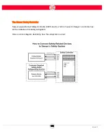
OPTIONAL SAFETY DEVICES
For differing levels of risk reduction, customers may add one or more safety-rated safeguarding
devices to create a monitored space in proximity to the robot.
For example, if a customer has an application where the robot must not move when a human is
required to approach within reach of the robot due to a hazard present in the work cell, and the
customer doesn't want to surround Sawyer with a safety cage, there are several other devices that
can be employed instead.
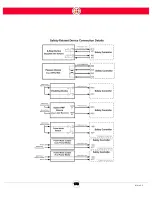
An optical sensor, like a laser scanner, usually placed at ankle height, senses people approaching,
and can act like an e-stop. When triggered, the device sends a signal to the Banner Safety
Controller, which triggers a category 0 stop.
Other devices in this category are light curtains and pressure-sensitive safety mats.
Support for Software Signals has been added for situations where the operator should leave the
work cell before resetting the robot. A three-button device positioned outside the safety space is
connected to the Banner Safety Controller by a cable. Its buttons are wired to correspond to the
software signals: Run From Here, Run From Start, and Re-Enable.
When the operator leaves the safety space and presses the Re-Enable button, for example, the
Banner Safety Controller receives that signal and closes the motor bus relays, making bus power
available to Sawyer's arm again. (This is the same effect as pressing OK on the Sawyer navigator to
Содержание Sawyer
Страница 15: ...8 Intera 5 3 Getting to Know Sawyer Hardware Overview of Your Robot ...
Страница 16: ...9 Intera 5 3 Getting to Know Sawyer Dimensions ...
Страница 17: ...10 Intera 5 3 Getting to Know Sawyer Sawyer Reach ...
Страница 21: ...14 Intera 5 3 Getting to Know Sawyer Bottom View Inputs Power Air Input Outputs 4x Air Power and Data Video ...
Страница 93: ...86 Intera 5 3 Train Pick and Place Patterns on the Head 11 Press OK to go to the next step ...
Страница 98: ...91 Intera 5 3 Train Pick and Place Patterns on the Head 16 Press OK to allow modifications to the direction ...
Страница 104: ...97 Intera 5 3 Train Pick and Place Patterns on the Head You may now run the task ...
Страница 134: ...127 Intera 5 3 TCP IP The Set To node in the Behavior Editor is used to output information ...
Страница 138: ...131 Intera 5 3 Fieldbus Devices 3 Using a keyboard navigate to CONFIGURATION and press ENTER ...
Страница 155: ...148 Intera 5 3 ...
Страница 156: ...149 Intera 5 3 ...
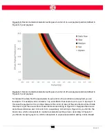
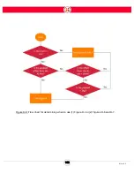
Страница 175: ...168 Intera 5 3 Figure D 8 Flow chart for determining when to use 1 Figure D 4 or 2 Figures D 6 and D 7 ...
Страница 180: ...173 Intera 5 3 ...
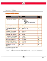
Страница 190: ...183 Intera 5 3 Fixed Data 112 From Robot ...
Страница 191: ...184 Intera 5 3 Standard Booleans 113 To Robot 114 From Robot Standard Integers 115 To Robot 116 From Robot ...
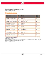
Страница 192: ...185 Intera 5 3 Standard Floats 117 To Robot 118 From Robot Small Booleans 119 To Robot 120 From Robot ...
Страница 193: ...186 Intera 5 3 Small Integers 121 To Robot 122 From Robot Small Floats 123 To Robot 124 From Robot ...
Страница 195: ...188 Intera 5 3 Large Floats 131 To Robot 132 From Robot Large Strings 133 To Robot 134 From Robot ...
Страница 206: ...199 Intera 5 3 Small Assembly 114 From Robot 115 To Robot ...
Страница 207: ...200 Intera 5 3 Large Assembly 116 From Robot 117 To Robot ...
Страница 208: ...201 Intera 5 3 Floats 118 From Robot 119 To Robot ...
Страница 209: ...202 Intera 5 3 Strings 120 From Robot 121 To Robot ...
Страница 218: ...Z Zero G button 16 17 Zero G mode 24 Zero Gravity mode 17 zoom reset 42 ...
Страница 219: ......
Страница 220: ...Last updated June 18 2018 Intera 5 3 User Guide Getting Started Rev A ...