


161
Intera 5.3
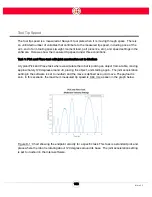
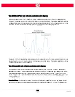
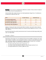
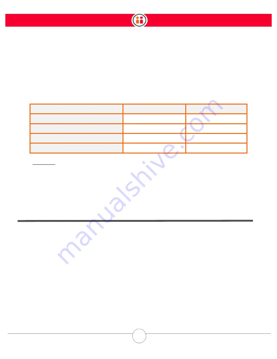
Overshoot - The overshoot is calculated as the difference in position of the end-effector measured
at the E-Stop time and the steady state time.
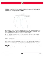
We also tested under multiple scenarios, and varied payload and voltage mode. The table below
summarizes the data from these runs.
Table D-1: E-Stop performance data for eight different conditions, varying the velocity mode and
the payload. The joint acceleration setting is set to
express
and the speed ratio is set to 1.0 in the
Intera software.
More information about low velocity mode can be found in the document titled
Sawyer Safety Over-
view: Low Power Mode
.
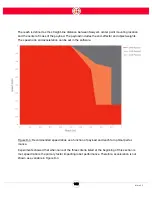
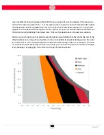
Payload vs. Reach
Depending on where Sawyer is in the workspace and how the end-effector is designed, the combi-
nation of speed, acceleration, reach and payload can have an impact on overall performance of the
robot. We can use Figure D-4 to represent the workspace in terms of speed ratio, acceleration,
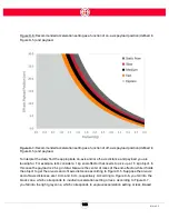
reach and payload, unless one of the following conditions is met:
•
The reach of the robot during a task is greater than 1 m;
•
The center of mass of the payload is offset from the J6 axis by more than 10 cm;
•
The payload offset from the J6 axis is greater than 2 kg.
MODE
SETTLING
TIME
(sec)
OVERSHOOT
(mm)
Low
velocity
mode/0
kg
payload
0.3
50
Low
velocity
mode/3.85
kg
payload
0.5
80
Normal
velocity
mode/0
kg
payload
0.2
80
Normal
velocity
mode/3.85
kg
payload
0.2
110
Содержание Sawyer
Страница 15: ...8 Intera 5 3 Getting to Know Sawyer Hardware Overview of Your Robot ...
Страница 16: ...9 Intera 5 3 Getting to Know Sawyer Dimensions ...
Страница 17: ...10 Intera 5 3 Getting to Know Sawyer Sawyer Reach ...
Страница 21: ...14 Intera 5 3 Getting to Know Sawyer Bottom View Inputs Power Air Input Outputs 4x Air Power and Data Video ...
Страница 93: ...86 Intera 5 3 Train Pick and Place Patterns on the Head 11 Press OK to go to the next step ...
Страница 98: ...91 Intera 5 3 Train Pick and Place Patterns on the Head 16 Press OK to allow modifications to the direction ...
Страница 104: ...97 Intera 5 3 Train Pick and Place Patterns on the Head You may now run the task ...
Страница 134: ...127 Intera 5 3 TCP IP The Set To node in the Behavior Editor is used to output information ...
Страница 138: ...131 Intera 5 3 Fieldbus Devices 3 Using a keyboard navigate to CONFIGURATION and press ENTER ...
Страница 155: ...148 Intera 5 3 ...
Страница 156: ...149 Intera 5 3 ...
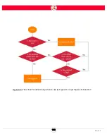
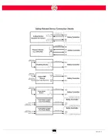
Страница 175: ...168 Intera 5 3 Figure D 8 Flow chart for determining when to use 1 Figure D 4 or 2 Figures D 6 and D 7 ...
Страница 180: ...173 Intera 5 3 ...
Страница 190: ...183 Intera 5 3 Fixed Data 112 From Robot ...
Страница 191: ...184 Intera 5 3 Standard Booleans 113 To Robot 114 From Robot Standard Integers 115 To Robot 116 From Robot ...
Страница 192: ...185 Intera 5 3 Standard Floats 117 To Robot 118 From Robot Small Booleans 119 To Robot 120 From Robot ...
Страница 193: ...186 Intera 5 3 Small Integers 121 To Robot 122 From Robot Small Floats 123 To Robot 124 From Robot ...
Страница 195: ...188 Intera 5 3 Large Floats 131 To Robot 132 From Robot Large Strings 133 To Robot 134 From Robot ...
Страница 206: ...199 Intera 5 3 Small Assembly 114 From Robot 115 To Robot ...
Страница 207: ...200 Intera 5 3 Large Assembly 116 From Robot 117 To Robot ...
Страница 208: ...201 Intera 5 3 Floats 118 From Robot 119 To Robot ...
Страница 209: ...202 Intera 5 3 Strings 120 From Robot 121 To Robot ...
Страница 218: ...Z Zero G button 16 17 Zero G mode 24 Zero Gravity mode 17 zoom reset 42 ...
Страница 219: ......
Страница 220: ...Last updated June 18 2018 Intera 5 3 User Guide Getting Started Rev A ...