


PROHP-EU Security System Control Panel
Installation Guide
This Installation Guide provides the basic steps to quickly and easily install the Burglar and Fire Alarm Control Panel, using the built-in
programming defaults. The control panel is designed for secure wall mounting. Refer to the full Installation Guide for additional information.
Follow the simple steps below to configure and install the ProSeries Control Panel.
Create a Customer Account
Registration, Programming and Testing is conducted through the AlarmNet 360™ cloud-based management platform using the Resideo
Pro App.
(Refer to page 3)
.
1.
Create a Customer Account using AN360 cloud-based management platform.
Connect the PROHP-EU
(refer to Figure 1 and 2)
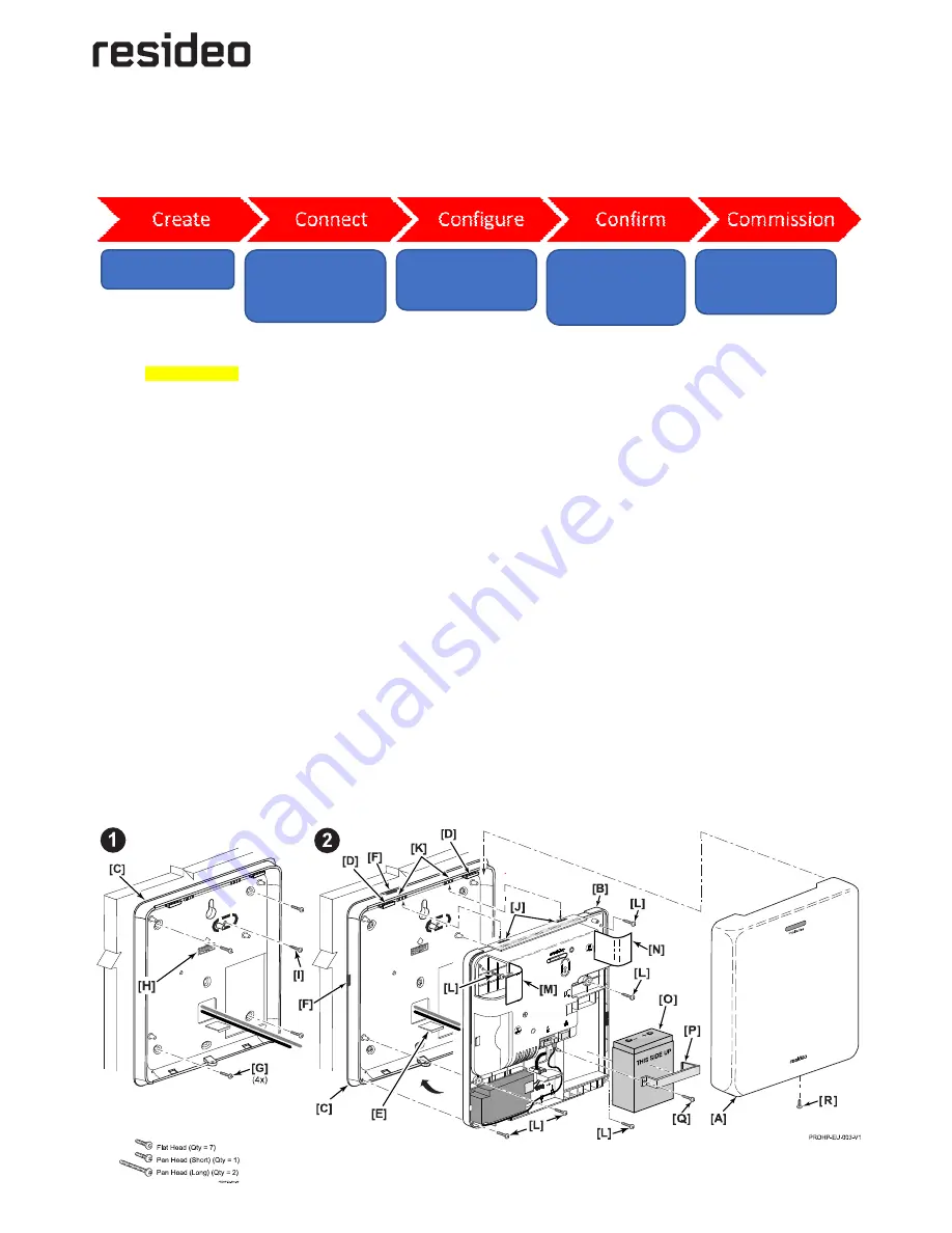
Select a location for the panel to maximize cellular signal level (if used) and wireless radio signal levels. Install the panel, as follows:
1. Remove the PROHP-EU cover
[A]
and separate the middle frame
[B]
and rear mounting plate
[C]
by releasing the upper
[D]
and
lower locking tabs
[E]
.
2. Route the system wiring and ethernet cable (if used) through the opening in the wall mount or through any of the knockouts (notch)
[F]
that are provided on each side of the mounting plate. Remove the thin plastic from the knockout (notch), if required. (refer to Figure
1). System wiring should extend 8-10cm through the opening. Refer to local regulations in your area for correct wire gauge and length.
3. Secure the rear mounting plate
[C]
to the wall with four screws
[G]
(not provided)
Use the integrated Bubble Level
[H]
to ensure the
panel is level).
4. Install the tamper screw
[I]
(not provided)
,
if required.
5. Insert the Control Panel Middle Frame to the mounting plate by aligning the slots
[J]
on the Middle Frame with the cleats
[K]
on the
mounting plate and sliding the unit up until the upper locking tabs
[D]
on the wall mount are engaged, then push it toward the wall to
engage the lower tab
[E]
and lock it in place.
6. Secure the middle frame to the mounting plate with six (6) provided flat-head screws
[L]
(open the Control’s left
[M]
and right
[N]
side
covers to access the upper points).
7. Open the Control’s left
[M]
and right
[N]
side covers, as required.
8. Install the PRO Series Communications Modules, as required and secure with the provided screws (Refer to Figure 2).
9. Insert the Battery Pack
[O]
into the mid-frame (ensure THIS SIDE UP on battery faces out) and install the retaining clip
[P]
. Secure the
battery clip with the provided short pan head screw
[Q]
.
10. Connect the red and black battery cables to the battery and the control panel + and – contacts.
11. Remove screw securing the clear cover on the power supply. Open the cover to gain access to the power supply terminals. Connect
the AC power source to the terminals.
Do not apply power at this time.
12. Connect the Power Supply DC connector and Ethernet cable (if used).
13. Install the plastic wire clamp and secure with (2) provided long pan head screws. If used, secure the Ethernet cable using wire ties.
14. Install the Control Panel Cover and secure it with the provided flat head set screw
[R]
.
Note:
Do not connect the control or router to a receptacle controlled by a switch. Allow up to 2 minutes for power-up.
15. Plug the power supply into a 230VAC outlet. Upon power-up the panel's blue LED illuminates. (Refer to Table 1 for LED Status)
Figure 1: Installing the Control Panel
Create a Customer Account
through AN360.
Install the Control Panel and
Power-up. Connect the
panel to a Communication
Source. Allow the System to
register with AN360.
Program the System
(Enroll Sensors, Keypads,
Keyfobs, Z-Wave, Users &
Settings)
Test the System and
confirm that all sensors
and devices are
operational and report to
the Central Station.
Commission the system
and train the Customer on
the proper use of the
ProSeries System.


