background image

INSTALLATION INSTRUCTIONS

33-00160EFS-05

HM700ADISTKIT

ELECTRODE STEAM HUMIDIFIER
DISTRIBUTION KIT

CAUTION

Before Servicing

1. Disconnect main power source before 

accessing internal compartments.

2. The plumbing and electrical compartments 

contain high voltage components and 
wiring. Access should be limited to licensed 
HVAC professionals only.

3. During and following operation of the 

humidifier, the steam components in 
contact with the steam such as the cylinder, 
steam lines, steam distributors, and 
condensate lines can become hot and burn 
if touched. Please consult HM700 
Installation manual for reference.

4. Humidity equipment installed by 

unqualified personnel or the use of parts 
and components not supplied with the 
humidifier or this kit will void warranty.

Steam Distributor

The HM700ADISTKIT is a remote mount, stainless 
steel steam distribution kit used with the HM700 
Electrode Steam Humidifier. The distributor is 
installed in a ventilation duct to distribute the steam 
produced by the HM700.

The HM700ADISTKIT consists of a steam distributor, 
steam hose, condensate hose, and installation 
hardware.

The steam distributor should be installed as close as 
possible to the humidifier. Short steam distribution 
lines minimize condensate loss and the possibility of 
generating backpressure in the steam distribution 
line.

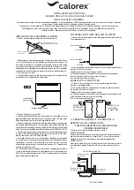
STEAM DISTRIBUTION

Steam generated by the humidifier may be 
introduced into the air in several different ways. The 
most common method for adding the steam into the 
air is to mount a steam distributor tube in a supply air 
duct as shown in Fig. 2.

STEAM LINE

The steam line between the cylinder steam outlet and 
the distributor serves two purposes: it is used as a 
conduit to transfer the atmospheric steam from the 
humidifier to the distributor, as well as providing a 
means to remove condensate. See “Steam Lines and 
Condensate Return Instructions” on page 2 f
or 
information on selecting steam lines.

CONDENSATE RETURN

Whenever steam is distributed condensate is formed 
in the distribution system. Insulating steam lines is 
one important way to reduce the amount of 
condensate formed. Steam lines are sloped so that 
condensate does not collect in the lines and create a 
restriction to steam flow. The condensate must be 
collected and removed from the system so that it does 
not build up and leak into the duct. Condensate can 
be returned to the HM700 fill cup to reduce water 
waste or can be fed to drain.

KIT CONTENTS:

• Stainless steel nozzle
• Insulated hose (5 ft.)
• Hose support brackets
• Screws
• Clamps
• Installation Instructions

TOOLS NEEDED (NOT SUPPLIED):

• Screwdriver
• Pliers  (optional)

Содержание Honeywell Home HM700ADISTKIT

Страница 1: ...am distribution lines minimize condensate loss and the possibility of generating backpressure in the steam distribution line STEAM DISTRIBUTION Steam generated by the humidifier may be introduced into the air in several different ways The most common method for adding the steam into the air is to mount a steam distributor tube in a supply air duct as shown in Fig 2 STEAM LINE The steam line betwee...

Страница 2: ...l remain trapped Steam naturally flows upward and condensate naturally flows downward 3 Ensure steam line properly supported so that no sags or dips are present 4 All bends should be done in large radius 12 in minimum Steam hose will soften when and may kick if too tight a radius is used which can cause a blockage and excessive back pressure 5 Horizontal runs of steam must rise 2 in per foot 10º w...

Страница 3: ...stallation Measurements in inches mm M35761 SPRING CLAMP 3 8 OD COPPER TUBE SPRING CLAMP INSERT HOSE OVER COPPER TUBE AND FASTEN WITH SPRING CLAMP M35825 8 203 MINIMUM 2X DUCT HEIGHT MINIMUM 2 3 DUCT HEIGHT MOUNT DISTRIBUTOR NOZZLE TO SIDE OF DUCT 4 FEET 1 2 M MINIMUM TO ANY OBSTRUCTION ...

Страница 4: ...s Measurements in inches mm For more information on maintenance and replacement please visit http honeywellhome com or call 1 800 468 1502 or 1 800 814 9452 M35717 CONNECT CONDENSATE HOSE TO FILL CUP 12 305 MINIMUM BEFORE ANY BEND 12 305 MINIMUM RADIUS CONDENSATE LINE SUPPORT BRACKETS 12 305 2 51 MINIMUM CONNECT STEAM HOSE TO CYLINDER CONDENSATE LINE 12 305 MINIMUM M35718 SUPPORT BRACKETS CONDENSA...

Страница 5: ... conduites de distribution de vapeur courtes réduisent la perte de condensat et le risque de contre pression dans la conduite de distribution de vapeur DISTRIBUTION DE VAPEUR La vapeur produite par l humidificateur peut être introduite dans l air de plusieurs manières La méthode d ajout de vapeur dans l air la plus courante consiste à monter un tube distributeur de vapeur dans un conduit d arrivée...

Страница 6: ...s 2 Assurez vous que le condensat produit dans la conduite de vapeur ne reste pas coincé La vapeur s écoule naturellement vers le haut et le condensat vers le bas 3 Veillez à ce que la conduite de vapeur soit bien supportée sans affaissement ni creux 4 Toutes les courbures doivent avoir un rayon minimum de 12 po Le tuyau de vapeur s assouplit avec le temps et peut se plier si le rayon est trop ser...

Страница 7: ...po mm MF35761 BRIDE À RESSORT TUBE EN CUIVRE DE 3 8 PO DE DIA EXT BRIDE À RESSORT INSÉREZ LE TUYAU SUR LE TUBE EN CUIVRE ET SERREZ AVEC LA BRIDE À RESSORT MF35825 8 203 MIN 2 X HAUTEUR DE CONDUIT MIN 2 3 DE LA HAUTEUR DU CONDUIT MONTEZ LA BUSE DU DISTRIBUTEUR SUR LE CÔTÉ DU CONDUIT 4 PIEDS 1 2 M MIN DE TOUTE OBSTRUCTION ...

Страница 8: ... le remplacement veuillez visiter http honeywellhome com ou appeler le 1 800 468 1502 ou le 1 800 814 9452 MF35717 CONNECTEZ LE TUYAU DE CONDENSAT À LA CUVETTE DE REMPLISSAGE 12 305 MINIMUM AVANT TOUTE COURBURE RAYON MINIMUM 12 305 CONDUITE DE CONDENSAT SUPPORTS DE RETENUE 12 305 2 51 MINIMUM CONNECTEZ LE TUYAU DE VAPEUR À LA BOUTEILLE CONDUITE DE CONDENSAT 12 305 MINIMUM MF35718 SUPPORTS DE RETEN...

Страница 9: ... de vapor cortas minimizan la pérdida de condensación y la posibilidad de que se genere una contrapresión en ellas DISTRIBUCIÓN DE VAPOR Es posible introducir el vapor generado por el humidificador en el aire de diferentes maneras El método más común para añadir el vapor en el aire es mediante la instalación de un tubo distribuidor de vapor en un conducto de suministro de aire tal como se muestra ...

Страница 10: ... naturalmente hacia arriba y el condensado fluye naturalmente hacia abajo 3 Asegúrese de que la línea de vapor se encuentre debidamente apoyada de modo que no se produzcan caídas o hundimientos 4 Todas las curvas deben presentar un radio amplio de 12 in como mínimo Si se utiliza un radio muy estrecho la manguera de vapor se ablandará y es posible que se doble lo que puede causar obstrucciones y un...

Страница 11: ...E RESORTE TUBO DE COBRE CON UN DIÁMETRO EXTERNO DE 3 8 ABRAZADERA DE RESORTE INSERTAR LA MANGUERA SOBRE EL TUBO DE COBRE Y FIJARLA CON LA ABRAZADERA DE RESORTE MS35825 8 203 COMO MÍN 2 VECES LA ALTURA DEL CONDUCTO COMO MÍN CONDUCTO CON UNA ALTURA DE 2 3 MONTE LA BOQUILLA DEL DISTRIBUIDOR EN EL EXTREMO LATERAL DEL CONDUCTO 4 FT 1 2 M COMO MÍN PARA EVITAR OBSTRUCCIONES ...

Страница 12: ...ormación sobre el mantenimiento y el reemplazo visite http honeywellhome com o llame al 1 800 468 1502 o al 1 800 814 9452 MS35717 CONECTA LA MANGUERA DE CONDENSADO AL RECIPIENTE DE LLENADO RADIO MÍNIMO DE 12 305 ANTES DE CADA CURVA RADIO MÍNIMO DE 12 305 LÍNEA DE CONDENSADO SOPORTES 12 305 2 51 COMO MÍNIMO CONECTAR LA MANGUERA DE VAPOR AL CILINDRO LÍNEA DE CONDENSADO 12 305 COMO MÍNIMO MS35718 SO...

Отзывы: