Emulation Adapter
Names and Functions of Hardware
R20UT4460EJ0110 Rev. 1.10
Page 21 of 53
Nov. 01, 2019
(2)
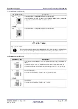
Switch: SW1 (POWER SW)
SW1 (POWER SW)
Specification
ON
(default)
This switch turns on the power supply of the base board.
Turn this switch on after connecting the emulation adapter and starting the
supply of power from CN2 of the emulation adapter.
OFF
This switch turns off the power supply of the base board.
CAUTION
Operating the switch:
Do not operate a switch before removing static electricity from the operator’s body. Doing
so may lead to the discharge of static electricity and so damage the internal circuits.
(3)
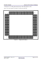
Switch: SW2 (RESET SW)
SW2 (RESET SW)
Specification
(L)
This position starts release from the reset state after the debug chip has been
reset.
The switch returns to the “H” position a moment after it stops being pressed.
The state of the reset pin of the debug chip changes from “L” to “H” (pulled up).
H
(default)
Reset released state.
The reset pin of the debug chip is in the “H” (pulled up) state.
L
Reset state.
The reset pin of the debug chip is in the “L” state.

