Emulation Adapter
Names and Functions of Hardware
R20UT4460EJ0110 Rev. 1.10
Page 18 of 53
Nov. 01, 2019
(7)
Jumper blocks: JP4 (EMUVCC) and JP5 (EMUVDD)
(8)
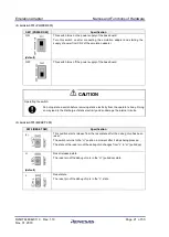
Jumper block: JP6 (AURORES)
JP6 (AURORES)
Specification
Open-circuit
AURORES pin = low
This setting is made when external tracing (Aurora tracing) is not to be used.
1-2 short-circuit
(default)
The AURORES pin is operated by the TRST pin.
When the emulator is connected, the level on the pin changes from low to high.
2-3 short-circuit
Setting prohibited.
AURORES pin = high
Check that the setting is consistent with the form of operation selected by JP4 and JP5.
(9)
Jumper block: JP7 (VDD)
JP7 (VDD)
Specification
Open-circuit
Setting prohibited.
1-2 short-circuit
(default)
The power generated on the emulation adapter is supplied as VDD for the debug
chip.
This setting must be made when the emulation adapter is to be connected to the
base board.
2-3 short-circuit
VDD on the target system is supplied as VDD for the debug chip.
When this setting is to be used, refer to notes in section 4.2.3.
JP4 (EMUVCC)
JP5 (EMUVDD)
Specification
Open-circuit
Open-circuit
Setting prohibited.
EMUVCC = OFF, EMUVDD = always ON
Open-circuit
1-2 short-circuit
Setting prohibited.
EMUVCC = OFF, EMUVDD = ON: Operation is with VCC.
Open-circuit
2-3 short-circuit
EMUVCC = OFF, EMUVDD = OFF
This setting is enabled when neither ERAM nor external
tracing (Aurora tracing) is to be used.
At the same time, make JP6 (AURORES) open-circuit.
Short-circuit
Open-circuit
Setting prohibited.
EMUVCC = ON, EMUVDD = always ON
Short-circuit
(default)
1-2 short-circuit
(default)
EMUVCC = ON, EMUVDD = ON: Operation is with VCC.
This setting must be made when ERAM or external tracing
(Aurora tracing) is to be used.
At the same time, make 1-2 on JP6 (AURORES) short-
circuit.
Short-circuit
2-3 short-circuit
Setting prohibited.
EMUVCC = ON, EMUVDD = OFF


