


CHAPTER 4 CPU ARCHITECTURE
Page 46 of 920
4.1.3
Internal data memory space
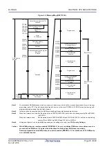
The internal RAM can be used as a data area and a program area where instructions are fetched (it is prohibited
to use the general-purpose register area for fetching instructions). Four general-purpose register banks
consisting of eight 8-bit registers per bank are assigned to the 32-byte area of FFEE0H to FFEFFH of the internal
RAM area.
The internal RAM is used as stack memory.
Caution 1. It is prohibited to use the general-purpose register (FFEE0H to FFEFFH) space for fetching
instructions or as a stack area.
Caution 2. Do not allocate RAM addresses which are used as a stack area, a data buffer, a branch
destination of vector interrupt processing, and a DTC transfer destination/transfer source to
the area FFE20H to FFEDFH when performing self-programming and rewriting the data flash
memory.
Caution 3. Use of the RAM areas of the following products is prohibited when performing self-
programming and rewriting the data flash memory, because these areas are used for each
library.
R5F11FLL: F3F00H to F4309H
Caution 4. The internal RAM area in the following products cannot be used as stack memory when using
the on-chip debugging trace function.
R5F11FLL: F4300H to F46FFH
4.1.4
Special function register (SFR) area
On-chip peripheral hardware special function registers (SFRs) are allocated in the area FFF00H to FFFFFH (see
4.2.4 Special function registers (SFRs)
Caution
Do not access addresses to which SFRs are not assigned.
4.1.5
Extended special function register (2nd SFR: 2nd Special Function
Register) area
On-chip peripheral hardware special function registers (2nd SFRs) are allocated in the area F0000H to F07FFH
(see
to
4.2.5 Extended special function registers (2nd SFRs: 2nd Special Function
Caution 1. Do not access addresses to which extended SFRs are not assigned.
Caution 2. When accessing timer RJ counter register 0 (TRJ0) allocated in F0500H of the extended SFR
(2nd SFR), the CPU does not proceed to the next instruction processing but enters the wait
state for CPU processing. For this reason, if this wait state occurs, the number of instruction
execution clocks is increased by the number of wait clocks. The number of wait clocks for
access to timer RJ counter register 0 (TRJ0) is one clock for both writing and reading.
Содержание RL78/G1H
Страница 941: ...R01UH0575EJ0120 RL78 G1H...


