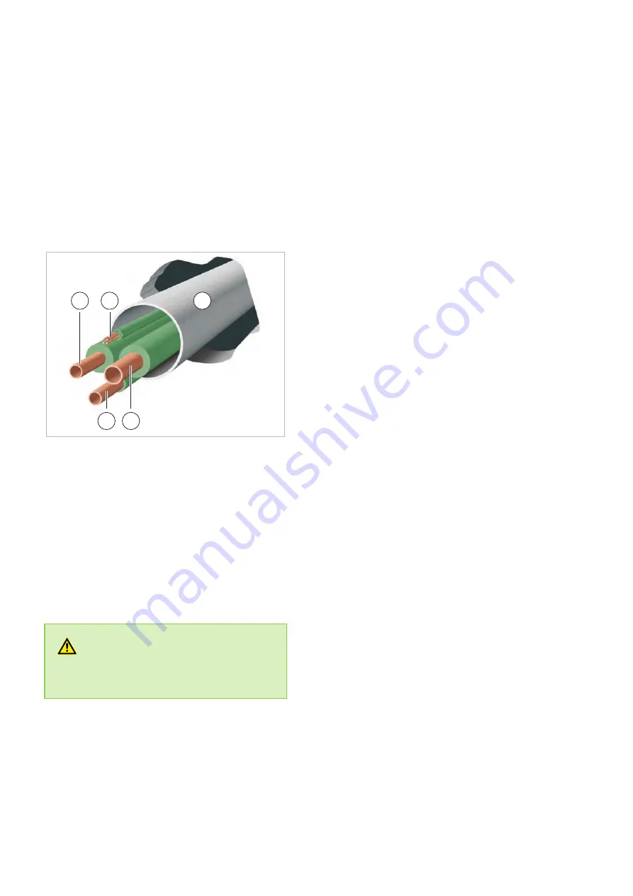
5.2 Wall openings
n
A wall opening of at least 70mm diameter and
10mm incline from the inside to the outside
must be created.
n
To prevent damage to the lines, the interior of
the wall opening should be padded or, for
example, lined with PVC pipe (see figure).
n
After installation has been completed, use a
suitable sealing compound to close off the wall
opening, taking account of fire protection regu-
lations (responsibility of customer). Do not use
cement or lime containing substances!
2
1
5
3
4
Fig. 11: Wall opening
1: Liquid line
2: Control line
3: Condensate drainage line
4: Suction pipe
5: PVC pipe
5.3 Installation materials
The outdoor unit is attached by 4 screws and a
wall bracket to the wall or fixed by a floor bracket to
the ground.
WARNING!
Only fasteners suitable for the given application
may be used.
5.4 Selection of installation
location
Indoor unit
The indoor unit is designed for horizontal wall
installation above doors. However, it can also be
used in the upper wall area (min. 1.75m above the
floor).
Outdoor unit
The outdoor unit is designed for horizontal installa-
tion on a base in outdoor areas. The installation
site must be level, flat and firm. The unit should
also be secured to prevent it from tipping over. The
outdoor unit can be set up outside as well as inside
a building. For external installation, please observe
the following notes to protect the unit from the
influence of the weather.
Rain
For floor or roof set-up, the unit should be installed
with at least 10cm ground clearance. A floor
bracket is available as an optional accessory.
Sun
The condenser on the outdoor unit emits heat.
Exposure to sunlight further increases the temper-
ature of the fins and reduces the heat released by
the finned heat exchanger. The outdoor unit should
be installed on to the north side of the building
whenever possible. If necessary, take measures to
provide sufficient shade (responsibility of cus-
tomer). One possible solution is to build a small
roofed area over the unit. These measures should
not affect the flow of warm outlet air.
REMKO series SKT
18
Содержание SKT 1060 AT
Страница 50: ...Resistance values for probes T1 T2 T3 T4 and T2B K Ohm K Ohm K Ohm K Ohm REMKO series SKT 50...
Страница 51: ...Resistance values for probe T5 K Ohm K Ohm K Ohm K Ohm 51...
Страница 61: ...61...
Страница 62: ...REMKO series SKT 62...
Страница 63: ......


