Operating and
installation instructions
Read the instructions prior to performing any task!
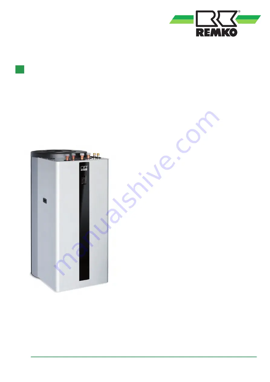
REMKO LWM series
LWM IM 300
Smart heat pumps
0259-2020-03 Edition 1, en_GB
Instructions for Technicians
Air/water system for heating or cooling
Страница 1: ...tallation instructions Read the instructions prior to performing any task REMKO LWM series LWM IM 300 Smart heat pumps 0259 2020 03 Edition 1 en_GB Instructions for Technicians Air water system for he...
Страница 2: ...these operating instructions carefully before commis sioning using this device These instructions are an integral part of the system and must always be kept near or on the device Subject to modificati...
Страница 3: ...2 Unit dimensions 9 3 Unit description 12 4 Installation instructions for qualified personnel 12 5 Hydraulic connection 14 6 Installation 17 7 Corrosion protection 20 8 Emergency heat operation 22 9 E...
Страница 4: ...be fatal or cause serious injury WARNING This combination of symbol and signal word warns of a potentially hazardous situation which if not avoided may be fatal or cause serious injury CAUTION This co...
Страница 5: ...s or floors n Mobile units must be set up securely on suit able surfaces and in an upright position Sta tionary units must be permanently installed for operation n The units and components should not...
Страница 6: ...and recycling Disposal of packaging All products are packed for transport in environ mentally friendly materials Make a valuable contri bution to reducing waste and sustaining raw mate rials Only dis...
Страница 7: ...t of indoor unit complete kg 143 Weight of storage tank kg 120 Hydraulic system technical data Medium flow rate water according to EN 14511 at t 5 K m3 h 0 95 Pressure loss outdoor kPa bar 80 0 08 Ope...
Страница 8: ...et temperature C 60 60 60 60 Hot water temperature C 50 50 50 50 Cold water temperature C 10 10 10 10 Heating cycle flow rate l h 600 1200 1800 2400 Throughput kW 18 7 28 1 33 7 37 0 Throughputs Stora...
Страница 9: ...2 2 Unit dimensions Dimensions indoor unit 1420 950 650 Fig 1 Indoor unit dimensions all dimensions in mm 9...
Страница 10: ...onnections 1 7 2 3 4 5 6 8 Fig 3 Designations of the pipe connections 1 Circulation 1 union nut flat sealing 2 Hot water 1 union nut flat sealing 3 Cold water inlet 1 union nut flat sealing 4 Heating...
Страница 11: ...in mm 1 Magnesium anode 2 PU insulation 3 Adjustable feet 4 Probe connection 1 2 5 Flange 6 Tilt height A Hot water B Inlet C Circulation D Return flow E Cold water Dimensions without the adjustable f...
Страница 12: ...ight of the indoor unit n The indoor unit is to be mounted in such a way that all of the sides have sufficient space for purposes of installation and maintenance It is equally important that there is...
Страница 13: ...cesses are dependent on one another however their separation from one another can vary greatly Corrosion cells can appear as a result of different potentials as the case is with contact corrosion Diff...
Страница 14: ...ng a buffer tank n Plan for air bleed valves and drain off taps at appropriate places n Flush the system s entire pipe network before connecting the heat pump n One or where necessary several expansio...
Страница 15: ...oor unit return flow water inlet 2 LWM outdoor unit inlet water inlet 3 Heating circuit inlet water inlet 4 Heating circuit return flow water inlet 5 Hot water connection 6 Cold water connection 7 Byp...
Страница 16: ...heating cycle pump and its speed is regulated according to requirements There is a pressure drop present on site see technical data If the pressure losses on site exceed this a separate storage tank e...
Страница 17: ...mperatures of 85 C avoiding possible damage Domestic hot water side connection pressure tight Hot water heaters are pressure tight storage tanks with which pressure tight connections can be establishe...
Страница 18: ...etween the safety valve and the cold water feed of the tank The safety valve must be set to a triggering pres sure which is below the nominal pressure of the storage tank After the conclusive connecti...
Страница 19: ...ghten the screws by hand n Then tighten the screws in the order specified below to a torque of 42 Nm 1 3 2 4 Fig 9 Fitting the flange installation port 1 Flange ring 2 Seal 3 Supporting disc 4 Flange...
Страница 20: ...nts in accordance with VDI 2035 Part 1 with regard to total hardness Total hardness dH subject to the specific system volume Total rated output in kW 20 l kW 20 l kW and 50 l kW 50 l kW to 50 kW 16 8...
Страница 21: ...ompliance is not covered by the guarantee Below you will find a suitable form for documenting the filling of the system Filling of heating system with completely deionised water Initial filling Year 2...
Страница 22: ...t be taken into account when designing the pump 8 Emergency heat operation If the outdoor unit fails you can start emer gency heat operation as follows 1 Pressing the REMKO logo in the top right corne...
Страница 23: ...consumers HGM HGU changeover valves etc to the I O module NOTICE Attach cables in accordance with the connec tion schematic and or the circuit diagram in the control box NOTICE Ensure correct polarit...
Страница 24: ...ly 230V 1 50Hz 4 Heater for anti freeze protection power supply 230V 1 50Hz 5 Modbus communication e g 3 x 1 0 mm2 sheathed 6 Power supply I O module 230V 1 50Hz 7 Power utility contact e g 2 x 1 0 mm...
Страница 25: ...3 A 4 3 A M M S14 S16 A22 23 5 2 4 2 A RC 1 S05 S08 2 3 4 B3 A3 RJ 45 PE PE N N L L A 2 D N G D N G A 2 p m u P t u O S F 2 B B 2 2nd mixed heating cycle NOTE without blocking contactor jumper must b...
Страница 26: ...1st mixed heating cycle return flow PT 1000 S12 X Probe 1st mixed heating cycle inlet PT 1000 S13 X Not connected S14 X Probe 2nd mixed heating cycle return flow S15 X Not connected S16 X Power utili...
Страница 27: ...X Not connected A32 X Enable 2nd Heat generator booster heating or boiler A33 X Not connected A34 X General alarm signal external A40 X Speed setting solar pump PWM A41 X Speed specification 1st mixed...
Страница 28: ...tial filling the discharge valve must be open The storage tank is fully filled when water which is free of bubbles starts to run out of the discharge pipe of the valve n The heat pump is not released...
Страница 29: ...e 1 Check all connections even those which were sealed at the factory flange anode sleeve for leak tightness 2 Then check all pipes for any leaks and if necessary eliminate these 3 Test the safety gro...
Страница 30: ...scale which forms inside the storage tank must be removed by a spe cialist after one to two years of operation Cleaning is performed through the flange opening 1 Drain the storage tank 2 Remove the he...
Страница 31: ...e heating cartridge at all poles 2 Drain the storage tank in areas where it is at risk from frost and before the onset of winter 3 After closing the shut off valve in the cold water supply the domesti...
Страница 32: ...high Observe temperature ranges Nominal temperature exceeded incor rect operating mode The set point temperature has to be higher than the heat generator temperature check mode Disconnect the outdoor...
Страница 33: ...spare parts 15 1 General view of unit and indoor unit spare parts 1 2 3 6 4 5 Fig 14 Exploded view of indoor unit We reserve the right to modify the dimensions and design as part of the ongoing techn...
Страница 34: ...od anode 1120230 Chain anode 1120121 SD card I O module current software without Smart Count and without Smart Web Upon request SD card Smart Control Touch current software without Smart Count and wit...
Страница 35: ...sign as part of the ongoing technical development process Storage tank spare parts list No Designation Storage tank EDP no 1 Fine tube heat exchanger 260200 2 Flange heating cartridge 260160 3 Immersi...
Страница 36: ...s ice is referred to as defrosting and is undertaken by supplying heat either regularly or as requirements dictate Air water heat pumps with circuit reversal are distin guished by their requirements b...
Страница 37: ...nces that deplete the ozone layer EC 2037 2000 and the Regulation on Cer tain Fluorinated Greenhouse Gases EC 842 2006 In addition a minimum of one annual service and inspection must be carried out as...
Страница 38: ...nnections on indoor unit arrangement 10 Pipe outlets on indoor unit spacing 10 S Safety Dangers of failure to observe the safety notes 4 General 4 Identification of notes 4 Notes for inspection 5 Note...
Страница 39: ......
Страница 40: ...5232 606 260 E mail info remko de URL www remko de REMKO GmbH Co KG Klima und W rmetechnik Im Seelenkamp 12 32791 Lage Hotline within Germany 49 0 5232 606 0 Hotline International 49 0 5232 606 130 W...