background image

1.6  Safety instructions for the oper-

ator

The operational safety of the units and compo-

nents is only assured providing they are used as

intended and in a fully assembled state.

n

The personnel tasked with operating the units

must check the units for visible defects on the

operating and safety devices as well as the

presence and function of the protective devices

prior to starting work.

If defects are discovered these must be

reported to the supervisor!

n

In the event of defects that endanger the

operational safety of the unit, operation must

be discontinued immediately.

n

Do not operate units or components with

obvious defects or signs of damage.

n

Observe the respective local regulations and

the relevant electrical safety measures when

using the units.

n

Safety devices must not be bypassed or disa-

bled.

n

Maintain safety distances to combustible mate-

rials.

n

Never insert foreign objects into the units.

n

The units must not be covered during opera-

tion.

n

The units must not be operated in the vicinity of

bathtubs, showers, swimming pools etc.

n

The units must not be operated directly below

a wall socket.

n

The units and components must not be

exposed to any mechanical load, extreme

levels of humidity or extreme temperatures.

n

Never allow water to enter the units.

n

Protective covers (grilles) over moving parts

must not be removed from units that are in

operation.

n

Contact with equipment parts or components

can lead to burns or injury.

n

All housing parts and unit openings, e.g. air

inlets and outlets, must be free from foreign

objects.

n

The air outlet must not be constricted or

equipped with pipe or hose lines.

n

All electrical cables for the units must be pro-

tected against damage, including damage

caused by animals.

n

The units must be inspected by a service tech-

nician to ensure that they are safe to use and

fully functional at least once yearly. Visual

inspections and cleaning may be performed by

the operator when the units are disconnected

from the mains.

1.7  Safety notes for installation,

maintenance and

inspection work

n

The units and components may only be set up,

installed and maintained by qualified per-

sonnel.

n

Appropriate hazard prevention measures must

be taken to prevent risks to people when per-

forming installation, repair, maintenance or

cleaning work on the units.

n

The setup, connection and operation of the

units and its components must be undertaken

in accordance with the usage and operating

conditions stipulated in this manual and comply

with all applicable regional regulations.

n

Regional regulations and laws must be

observed.

n

The units must be installed and operated in

such a way that personnel are not endangered

by warm air and radiant heat and that no fires

can occur

n

A safety zone of 1.5 m should be maintained

around the units - including non-combustible

items

n

The power supply should be adapted to the

requirements of the units.

n

Mobile units must be set up securely on suit-

able non-combustible surfaces.

n

The units and components should not be oper-

ated in areas where there is an increased risk

of damage. Observe the minimum clearances.

n

The units and components must be kept at an

adequate distance from flammable, explosive,

combustible, abrasive and dirty areas.

n

The units must not be installed or operated in

atmospheres containing oil, sulphur or salt.

n

The units must not be exposed to direct jets of

water, e.g. pressure washers etc.

n

Safety devices must not be bypassed or disa-

bled.

1.8  Unauthorised modification

and changes

Modifications or changes to units and components

are not permitted and may cause malfunctions.

Safety devices may not be modified or bypassed.

Original replacement parts and accessories

authorised by the manufactured ensure safety. The

use of other parts may invalidate liability for

resulting consequences.


5

Содержание ELT 40

Страница 1: ...erating instructions Read the instructions prior to performing any task REMKO ELT series ELT 40 Electric heater 0199 2018 10 Edition 1 en_GB This product is suitable only for well insulated rooms or for occasional use ...

Страница 2: ...ig inal Read these operating instructions carefully before commis sioning using this device These instructions are an integral part of the system and must always be kept near or on the device Subject to modifications No liability accepted for errors or mis prints ...

Страница 3: ...d modification and changes 5 1 9 Intended use 6 1 10 Warranty 6 1 11 Transport and packaging 6 1 12 Environmental protection and recycling 6 2 Technical data 7 2 1 Unit data 7 3 Design and function 8 3 1 Unit description 8 4 Electrical wiring 9 4 1 Electrical wiring diagram 9 5 Commissioning the unit 10 6 Shutdown 11 7 Troubleshooting and customer service 12 8 Care and maintenance 13 8 1 General 1...

Страница 4: ... be fatal or cause serious injury WARNING This combination of symbol and signal word warns of a potentially hazardous situation which if not avoided may be fatal or cause serious injury CAUTION This combination of symbol and signal word warns of a potentially hazardous situation which if not avoided may cause injury or mate rial and environmental damage NOTICE This combination of symbol and signal...

Страница 5: ...hat they are safe to use and fully functional at least once yearly Visual inspections and cleaning may be performed by the operator when the units are disconnected from the mains 1 7 Safety notes for installation maintenance and inspection work n The units and components may only be set up installed and maintained by qualified per sonnel n Appropriate hazard prevention measures must be taken to pr...

Страница 6: ...de special agreements beyond these conditions In this case contact your contractual partner in the first instance 1 11 Transport and packaging The devices are supplied in a sturdy shipping con tainer Please check the equipment immediately upon delivery and note any damage or missing parts on the delivery and inform the shipper and your contractual partner For later complaints can not be guaranteed...

Страница 7: ... consumption at nominal heating power elmax kW 37 5 Auxiliary current consumption at minimum heating power elmin kW 16 5 Auxiliary current consumption in standby condition elSB kW 0 005 Fuse protection provided by the customer slow blow A 64 Sound pressure level LpA 1m 1 dB A 74 Dimensions length width height mm 1410 560 775 Type of room temperature control electronic external Weight kg 81 5 EDP n...

Страница 8: ... temporary room heating n De icing machines vehicles and non combus tible warehoused goods while adhering to the relevant safety distances Operating sequence The units can be used in the respective modes for air heating and air circulation purposes They can be operated on three heating settings and one fan setting They have a 5 stage operating switch with the functions Off 0 Ventilation 1 Heating ...

Страница 9: ...otor protection 2 K3 K5 Contactor for heating stages KX6 Phase sequence relay 1 KX7 Phase sequence relay 2 KX8 Time relay M1 Fan motor RT Room thermostat socket S1 Operating switch S4 Aftercooler thermostat NK S6 Temperature controller TR S7 Safety temperature limiter STB X3 Terminal block We reserve the right to modify the dimensions and design as part of the ongoing technical development process...

Страница 10: ...tch to the 0 off position 3 Connect the unit s power plug to a properly installed mains socket The electrical connection for the units must be made at a separate feedpoint with a residual current device in accordance with VDE 0100 Section 55 NOTICE Extensions to the connection cable must only be conducted by authorised specialist electri cians taking into consideration the unit power consumption c...

Страница 11: ...om The thermostat sensor must not be located directly in the warm air flow and must not be placed directly on a cold floor 4 Set the desired temperature on the room thermostat 4 4 5 Select the desired power position on the operating switch 6 Shutdown 1 Switch the operating switch to the 0 off position The supply air fan runs on to cool the units and only switches off after the cooling down phase i...

Страница 12: ...hecked against the following list Please inform your dealer if the unit is still not working correctly after all of the functional checks have been performed The unit fan does not start 1 Check the mains fuses provided by the cus tomer 2 Check the power plug 3 Check the operating switch 4 Check that the fan can move freely The unit does not heat up 1 Check the operating switch 2 Check that the con...

Страница 13: ...n use only suit able cleaners n Check the inlet and outlet grille for contamina tion on a regular basis n Check the units for mechanical damage and have defective parts properly replaced n Check that the safety devices and the protec tive devices are operating correctly at regular intervals n Keep the probe for the safety devices free of dust and dirt n Be careful not to damage the temperature lim...

Страница 14: ... Date Signature 02 Date Signature 03 Date Signature 04 Date Signature 05 Date Signature 06 Date Signature 07 Date Signature 08 Date Signature 09 Date Signature 10 Date Signature 11 Date Signature 12 Date Signature 13 Date Signature 14 Date Signature 15 Date Signature 16 Date Signature 17 Date Signature 18 Date Signature 19 Date Signature 20 Date Signature Have the forced air burner maintained and ...

Страница 15: ...view of the unit and spare parts list 9 1 Exploded view of the unit Fig 5 Exploded view of the unit We reserve the right to modify the dimensions and design as part of the ongoing technical development process 15 ...

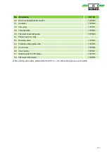
Страница 16: ...102794 18 V belt pulley motor 1102794 19 Back wall 1107979 20 Protective intake grille rear 1107980 21 Motor plate 1107981 22 Radial fan 1108610 23 Connection terminal strip 1107982 24 Strain relief 1107983 25 Connection cable with plug 1107893 27 Safety thermostat with probe 1101197 28 Strapping plug 1101019 29 Thermostat socket complete 1101018 30 Control fuse complete with holder 1107984 31 Eme...

Страница 17: ...0 Thermal cut out with probe 1107960 41 Phase sequence relay 42 Mounting plate 1107894 43 Protective intake grille side 1107895 45 Centre wall 1107896 46 Inner casing 1107897 47 Retaining clip for STB probe 1101395 48 Aftercooler thermostat 1104065 When ordering spare parts please state the EDP no unit number and type see name plate 17 ...

Страница 18: ...e safety notes 4 General 4 Identification of notes 4 Instructions for the operator 5 Note for inspection work 5 Note for installation work 5 Note for maintenance work 5 Personnel qualifications 4 Safety conscious working 4 Unauthorised modification 5 Unauthorised replacement part manufacture 5 W Warranty 6 REMKO ELT series 18 ...

Страница 19: ......

Страница 20: ...ct as advisers to our customers in air conditioning and heating technology SFlbCustomer Service Our equipment operates precisely and reliably However in the event of a fault REMKO customer service is quickly at the scene Our comprehensive network of experienced dealers always guarantees quick and reliable service REMKO INTERNATIONAL and also right in your neighbourhood Make use of our experience a...

Отзывы: