
1
CN
2011
INSTALLATION INSTRUCTIONS FOR
MODELS JR-3 & JR-4
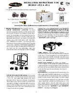
This package contains the following factory supplied parts:
QUICK TOUCH TIMER
CORD SET
TWO STEAM NOZZLES & ESCUTCHEONS
WATER INLET
JR-3 or JR-4
QUICK TOUCH TIMER SWITCH
(Packaged inside electrical box)
Use only the Relax-A-Mist factory supplied parts in this package!
1. GENERAL INFORMATION
(See “SELECTION” p.5).
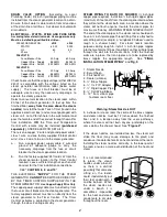
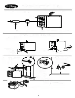
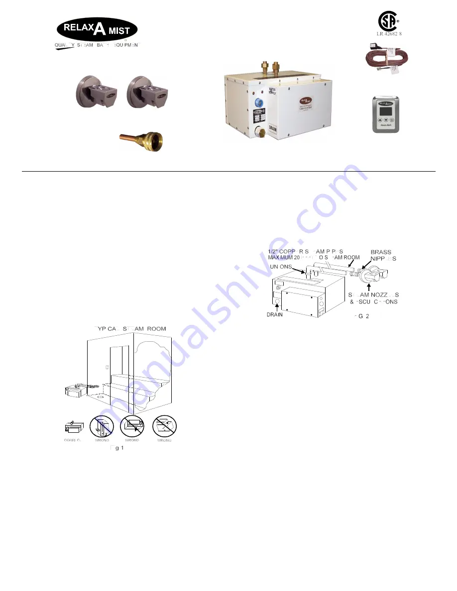
STEAM GENERATOR LOCATION
The steam
generator should be located in a ventilated area outside
of, but within 20 feet of the shower or steam room,
where the steam pipes can be installed without the
possibility of a steam trap. The steam generator may
be placed under the floor, in a closet or any convenient
location where it WILL BE LEVEL, DRY, AND WILL
NOT FREEZE in the winter. The steam generator
MUST be easily accessible should service be required
in the future. INSTALL THE STEAM GENERATOR
WITH THE COPPER STEAM PIPES COMING OUT
OF THE TOP OF THE APPLIANCE AND THE
ELECTRICAL BOX FACING THE ACCESS! See
Fig1
.
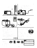
STEAM PIPES AND STEAM NOZZLE
(To and in the
Steam Room) The steam pipes must be a minimum of
½ inch I.D. rigid copper pipe between the steam
generator and the area to be steamed. Installing the
steam pipes using the most direct or shortest route
(WITHOUT FORMING A STEAM TRAP) and with the
fewest number of elbows will, in most cases, maintain
a lower pressure (less than 1 lb) in the boiling tank than
a longer route with many elbows.
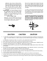
CAUTION: There is to be NO RESTRICTION in the STEAM PIPES
BETWEEN the STEAM GENERATOR and the STEAM NOZZLES that
would in any way cause PRESSURE to build in the STEAM
GENERATOR. INSTALL the STEAM NOZZLE 12" above the finished
flooring, in a LOCATION where the STEAM WILL NOT BURN anyone.
During the final installation, the steam nozzles supplied
MUST be used. See “Steam Piping to Bath or Shower”.
“CAUTIONS 1 and 3"
and
Fig. 2
.
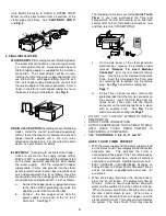
TIMER SWITCH
(Steam Generator Control.)
The Quick Touch Timer can be located inside or outside the
steam room. If using the optional Time and Temperature
Control, refer to that control's installation instructions now.
Relax-A-Mist Timer Switches are not a precision timing
device. See
“CAUTION 11”
DRAIN VALVE OPTION
(Ask Dealer For Details)
A 3/4 inch copper, female adapter (located below the water
supply connection), can be plumbed to a drain with either a
manual shut off or an automatic drain valve installed at the
steam generator (purchased separately) See Figure 2.
2. ROUGH-IN
WATER SUPPLY
(According to Local Plumbing Code) The
water supply pipe should be equipped with a shut off that is
accessible and close to the steam generator. Installation of
a water hammer arrester (water bumper) is recommended.
To maintain a proper water level in the generator the water
supply should have a minimum of 20 lbs pressure. If the
water supply contains impurities that could cause scale
build-up or corrode the steam generator, install appropriate
water treatment. See
“CAUTION 4" and “WARRANTY
POLICY”
. See diagrams on
Page 6
.


