background image

Montageanleitung / instruction sheet  / Notice de montage / Istruzioni di montaggio / Instrucciones de montaje 

HKV / HKV-D 


Stand 02/2009 

EDV-Nr. 7002059 

Technische Änderungen vorbehalten / subject to technical modification / sous réserve des 

modifications techniques / Salvo modifiche tecniche / Salvo modificaciones técnicas 

2


GB


INFORMATION. Instructions for use 

and important information. 


BEWARE! Important information about 

function. Failure to heed can impair 

function. 


Legal information. 


Personnel requirements


Prior to starting work, the fitter must read, under-

stand and heed these installation and operating 

instructions. 

HKV / HKV-D manifolds for underfloor heating 

may only be installed, adjusted and maintained 

by trained specialists. Trainees may only work on 

the product under the supervision of an experi-

enced person. Only if the above instructions 

have been adhered to will the manufacturer ac-

cept any liability in line with statutory provisions. 

Every instruction contained in these installation 

and operating instructions is to be heeded when 

using the HKV / HKV-D manifolds. 


 Correct use 


HKV / HKV-D manifolds are used for distributing 

and regulating the volume of flow in low tem-

perature underfloor heating systems and under-

floor cooling systems. 


HKV / HKV-D manifolds are to be operated using 

heating water as per VDI 2035. In the case of 

systems, the heating water of which contains 

corrosive particles or other contaminants, dirt 

traps or filters with a mesh size of no more than 

0.8 mm are to be fitted in order to protect the 

measuring and control devices. 

The max. permissible continuous operating pres-

sure is 6 bar at 80 °C. The max. permissible test 

pressure is 8 bar at 20 °C. 

Using the manifolds for any purpose other than 

that set out in these instructions constitutes im-

proper use. The manufacturer accepts no liability 

for damage resulting from improper use of the 

manifolds. 

For safety and guarantee reasons, no conversion 

or modification is permitted. 

The manufacturer accepts no liability if connec-

tions and accessories made by other manufac-

turers are used. 


              Installation / Commissioning 


Installation in manifold cabinet: 

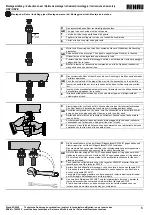
The manifold headers are fitted to the sliding C 

profile rails, using the supplied bolts. Please 

heed the relevant installation instructions. 


Wall installation: 

The HKV / HKV-D manifolds are fitted using the 

installation kit provided (4 x S 8 rawl plugs and 4 

screws 6 x 50)  


Hydraulic connections: 

HKV / HKV-D manifolds are supplied with a 1” 

ball valve set plus a flush-and-fill unit (SBE).  


The manifold headers each have a G 1” male 

thread for fitting the ball valve and the flush-and-

fill unit, with flat joints. The union nuts are to be 

tightened with an SW 38 ring spanner or open-

ended spanner with approx. 35 - 45 Nm. When 

connecting pipes to connections, please see our 

pipe installation instructions.  

The heating circuits for the individual rooms are 

labelled with the self-adhesive labels provided. 

These can be stuck to the manifold itself. 


Flushing and filling the heating circuits: 

Hoses with 3/4” connections tubes are screwed 

to the hose of the feed taps to fill the heating cir-

cuit manifold. Slowly open and close the valves 

connections to operate the flush-and-fill unit. 


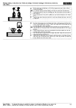
 Beware! 


During the filling and flushing process, the 1” ball 

valves on the flow and return headers must re-

main closed, otherwise the high water pressure 

might damage the heating system or might acti-

vate the safety valve. 

Only fill and flush the manifold in the direction of 

flow! Please avoid high differential pressure (> 1 

bar) and pressure shocks. 


Содержание HKV

Страница 1: ... Verwendung ist nicht bestimmungsgemäß Für die aus missbräuchlicher Verwendung der Heiz kreisverteiler entstehenden Schäden haftet der Hersteller nicht Umbauten oder Veränderungen sind aus Grün den der Sicherheit und Gewährleistung nicht zu gelassen Eine Gewährleistung bei Verwendung von Ver schraubungen und Zubehörteilen anderer Her steller kann nicht übernommen werden Montage Inbetriebnahme Mont...

Страница 2: ... 20 C Using the manifolds for any purpose other than that set out in these instructions constitutes im proper use The manufacturer accepts no liability for damage resulting from improper use of the manifolds For safety and guarantee reasons no conversion or modification is permitted The manufacturer accepts no liability if connec tions and accessories made by other manufac turers are used Installa...

Страница 3: ...ns que celle décrite dans ce document sont interdites Les désordres en gendrés suite à une mauvaise utilisation du col lecteur ne pourront pas être imputés au fabri cant Transformer ou modifier le collecteur est interdit pour des raisons de sécurité et de bon fonction nement L utilisation d autres raccords ou accessoires d un autre fabricant avec notre collecteur ne sera pas couverte par notre gar...

Страница 4: ...I declina ogni responsabilità per danni di qualsivoglia natura dovuti a uso errato o non conforme del collettore Per motivi di sicurezza è vietato effettuare eventuali trasformazioni e o modifiche di propria iniziativa In caso di utilizzo di collegamenti a vite e o accessori di altra marca decade il diritto alla garanzia Montaggio messa in funzione Montaggio all interno dell armadietto di distribu...

Страница 5: ...rita en estas instrucciones es considerada como no conforme con la finalidad de uso El fabricante no responde de los daños ocasionados por la utilización indebida de los colectores Por motivos de seguridad y de garantía no está permitido transformar o modificar el colector No se asume garantía legal alguna en caso de utilizar racores y accesorios de otros fabricantes Montaje Puesta en marcha Monta...

Страница 6: ...me des Verteilers aufschrauben Das Rohr dabei mit der anderen Hand bis zum Anschlag gedrückt halten GB Screw the compression nut by hand onto the connection on the manifold Whilst doing so keep the pipe pushed all the way in with the other hand F Serrer d une main l écrou du raccord au collecteur Pousser avec l autre main le tube en butée I Avvitare manualmente il dado dell anello di bloccaggio su...

Страница 7: ...o el husillo regulador hacia la izquierda abrir Efectuar el número de vueltas de acuerdo con el dimensionamiento o basado en el diagrama_1 D Die schwarze Schutzkappe nach Beendigung der Einstellung wieder aufsetzen da mit ungewollte Fremdeinwirkung oder Verschmutzung der Ventile verhindert wird GB Once the adjustments have been made replace the black protective cap to prevent any accidental adjust...

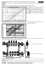
Страница 8: ...ngitud L mm 190 245 300 355 410 465 520 575 630 685 740 795 850 Druckverlust pressure drop Perte de charge total Perdite di carico Pérdida de carga mbar Drehungen offen turns open Ouvertures Numero rotazioni apertura Vueltas abierto Volumenstrom flow rate Volume Portata volumetrica Caudal volumétrico l h Druckverlust pressure drop Perte de charge total Perdite di carico Pérdida de carga mbar Volum...

Страница 9: ...gramme 2 I Regolare la portata ruotando la vite di regolazione in senso antiorario Il numero di rotazioni necessarie va stabilito utilizzando la documentazione di progettazione op pure dal diagramma _2 E El caudal volumétrico se ajusta girando el husillo regulador hacia la izquierda El valor real se lee en el caudalímetro de la impulsión Efectuar el número de vueltas según dimensionamiento o basad...

Страница 10: ...os de mantenimiento el circuito de calefacción puede ser cierre vía el flujómetro D Die blaue Schutzkappe bzw der Stellantrieb sollte nach Beendigung der Einstellar beiten wieder aufgeschraubt werden Hiermit wird ungewollte Fremdeinwirkung oder Verschmutzung der Ventile verhindert GB Once adjustment work is complete the blue protective cap actuator should be screwed back on This prevents the valve...

Страница 11: ...Longitud L mm 190 245 300 355 410 465 520 575 630 685 740 795 850 Volumenstrom flow rate Volume Portata volumetrica Caudal volumétrico l h Druckverlust pressure drop Perte de charge total Perdite di carico Pérdida de carga mbar Drehungen offen turns open Ouvertures Numero rotazioni apertura Vueltas abierto 1 10 100 1 000 100 1 000 10 000 2 3 4 5 6 7 12 1 Druckverlust pressure drop Perte de charge ...

Страница 12: ... que l application l utilisation et la mise en œuvre de nos produits s effectuent en dehors de notre contrôle elles n engagent que votre seule responsabilité Si malgré tout notre responsabilité venait à être mise en cause elle serait limité à la valeur de la marchandise que nous avons livrée et que vous avez utilisée No tre garantie porte sur une qualité constante de nos produits conformément à no...

Отзывы: