WARNING: Installation,
disassembly, repair and
maintenance MUST be
performed only by qualified
personnel. All gas MUST be evacuated from the system before
starting repairs.
Installation, usage and maintenance of this product must be in
compliance with all RegO
®
instructions as well as requirements
and provisions of NFPA #54, NFPA #58, DOT, ANSI, all applicable
federal, state, provincial and local standards, codes, regulations
and laws.
Inspection and maintenance on a periodic basis is essential.
Be sure all instructions are read and understood before instal-
lation, operation and maintenance. These instructions must be
passed along to the end user of the product.
RegO Rail Tank Car equipment is AAR approved. If repaired, the
continued validity of the AAR approval is contingent upon proper
inspection to determine what needs to be repaired; proper repair
using RegO OEM parts and procedures, proper testing for leakage
and performance following repairs and installation.
ECI EXPRESSLY DISCLAIMS ANY AND ALL LIABILITY – UNDER
ANY THEORY, WHETHER CONTRACT, WARRANTY, TORT OR
OTHERWISE – RELATING IN ANY MANNER TO ANY RAIL TANK
CAR EQUIPMENT REPAIRED USING ANY PRODUCTS NOT MANU-
FACTURED BY ECI.
USE OF ANY PRODUCTS NOT MANUFACTURED BY ECI TO RE-
PAIR ANY RAIL TANK CAR EQUIPMENT WILL INVALIDATE ANY
AND ALL WARRANTIES OF THE RAIL TANK CAR EQUIPMENT,
WHETHER EXPRESS OR IMPLIED.
CAUTION: Contact or inhalation of liquid propane, ammonia and
their vapors can cause serious injury or death! NH
3
and LP-Gas
must be released outdoors in air currents that will insure disper-
sion to prevent exposure to people and livestock. LP-Gas must
be kept far enough from any open flame or other source of ignition
to prevent fire or explosion! LP-Gas is heavier than air and may
not disperse or evaporate rapidly if released in still air.
Disassembly and Rebuild Procedure
CAUTION: READ THROUGH ALL OF THESE INSTRUCTIONS,
INCLUDING THE NOTICE AND WARNINGS ON THE BACK OF THIS
SHEET, BEFORE BEGINNING ANY DISASSEMBLY OR REPAIR.
NOTE: Repairs must be performed in a clean area. Hands, cloth-
ing, tools and work area must be completely free of oil, grease
and foreign matter to prevent contamination of component parts
and valves.
Disassembly
1. Evacuate contents of tank prior to disassembly.
2. Remove valve from railcar and place on a stable surface.
3. Using a 1/2” wrench, turn the adjusting hex nut clockwise to
compress the spring.
4. Continue to turn the hex nut until there is enough room between
the nuts to allow the stem to be cut.
5. Cut the stem between the two nuts and discard the cut end.
6. Place the valve in a press. Compress against the spring
retainer to compress the spring.
7. Remove the hex nut from the stem and discard.
8. Slowly remove pressure from the spring retainer and spring
and remove valve from the press.
9. Remove the spring, spring retainer and washer (if present)
and retain.
10. Slowly remove the poppet and stem assembly from the body
and discard.
CAUTION: Make sure not to damage the seat area in the body
when removing the poppet.
Inspection
Inspect all retained parts for signs of wear and deterioration. Pay
special attention to the surface finish of the valve seat as well as
the condition of the spring. Replace parts as necessary**.
Reassembly
1. Paying special attention not to contact the seat, slowly install
the new stem assembly through the body seat and stem guide
until the poppet seal contacts the seat.
2. Reinstall the washer (if present), spring and spring retainer.
3 Install valve in a press (recommended) and compress the
spring retainer to compress the spring to a height of 4.75”.
4. Using only the hex nut, engage until nut contacts spring retainer.
5. Remove the valve from the press.
Testing
1. Allow valve to sit at least 24 hrs after assembly to allow for
proper seat compression.
2. Attach valve to test fixture.
3. Fill outlet with water and observe pressure gauge as pressure
is raised. After pressure is raised to within 25 psi of the set
pressure marked on the valve, begin to increase pressure at
a rate no greater than 2 psi per second until the first bubbles
through the water seal are observed. If bubbles do not ap-
pear at proper start-to-discharge pressure, tighten or loosen
the hex nut until bubbles indicate proper setting.
4. After correct start-to-discharge pressure is reached, shut off
inlet pressure. Observe at what pressure valve seals off.
Valve must reseal by 80% of start-to-discharge setting.
5. Exhaust air pressure and remove valve from fixture.
6. Affix hex nut in place using one of the following methods:
a. Install lock nut and torque to 65-70 in-lbs, then mark both
nuts to ensure no adjustment upon inspection. See Figure
1.
b. Spot weld hex nut to stem per approved WPS. No lock
nut shall be used with this method. See Figure 2.
7. Reinstall the rain cap.
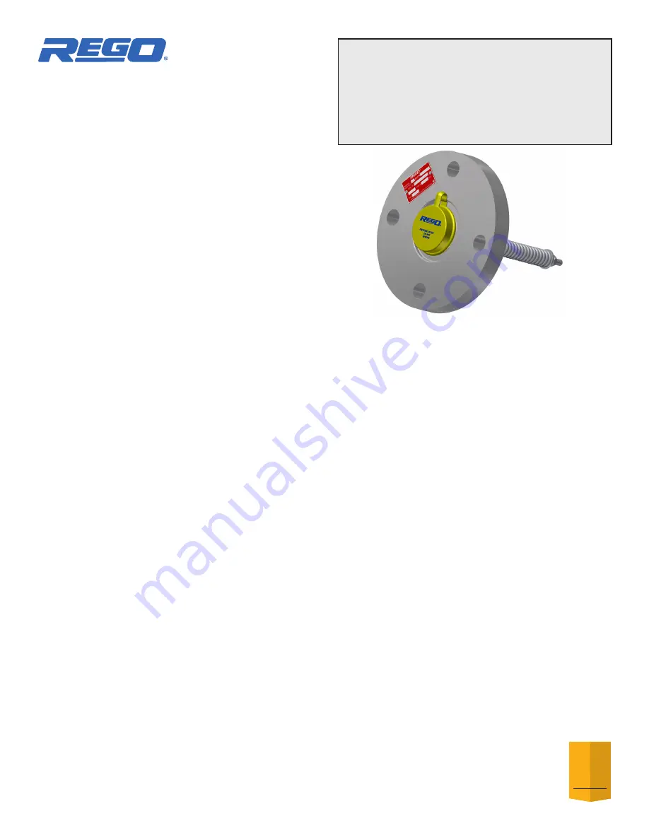
A8434F-50 (Nitrile) and
VA8434F-50 (Viton) Rebuild Kits
for A8434F and A8434FA Series
Flange Mount
Internal Relief Valves
10
R EG O
Y E A R
WARRANTY


