


www.
reefe
.com.au
Ascento Group Australia
©
AI.062020
P: 1800 807 604
WARRANTY AND RECOMMENDATIONS
The product is guaranteed the first 2 years after its production date.
This guarantee does not include damages in case of an inadequate installation or manipulation.
Carefully read this instructions manual before installation.
Do not throw away this manual after installation, it can be useful for later modifications or for solving the different types of alarms.
Hydraulic and electrical installations must be set up by qualified personnel according to the safety prescriptions as well as the standards and legisla-
tion of every country. When carrying out the electrical connection it is recommended to use a differential switch of high sensitivity: I
Δ
n = 30 mA (class
A o AC). It is recommended to use a 20 A (VSC1-12/VSC3-14), 10A (VSC1-10) or 16A (VSC3-9) magneto thermic switch. It is recommended to use an
independent electrical line, with the purpose of avoiding electromagnetic interferences that could create non wished alterations in household electronic
devices.
WARNING, before doing any maintenance inside the device, it must be unplugged from the electric supply and wait a minimum of 2 minutes after the
disconnection to avoid electrical discharges.
WARNING SYMBOLS CONTAINED IN THIS SERVICE MANUAL
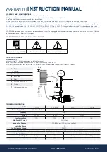
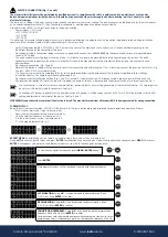
INSTALLATION SCHEME
OBSERVATIONS
a) Accessories (3, 4, 8) are recommended, but not essential
b) In the case of the hydropneumatics tank (7), minimum capacity should be 5L.
c) A pressure transmitter must be installed (5), output 4-20mA, with pressure range either 0-10bar or 0-16bar.
WARRANTY |
INSTRUCTION MANUAL
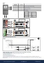
Only applies to type MASTER
Risk by electric shock
Risk for people and/or objects
230 V
min.
5 l
400 V*
Fig. 2
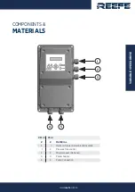
# Part
1
Pump
2
Check Valve
3,8
Ball Valve
4
Filter
5
Pressure transmitter
6
Device
7
Hydropneumatic Tank
MODEL
VSC1-10
VSC2-12-240
VSC3-9
VSC3-14
Power Supply Voltage
˜1X240 Vca±10%
Frequency
50Hz
Output
˜3X240
˜1X240
˜3X400
Max. Current Each
10A
12A
9A
14A
Max. Peak of Current
20% 10 Sec
Range of Set Pressure
0.5-16 Bar or 0.5-10 bar (type config.)
Protection Degree
IP55
Max. Environment Temp.
5-40°C
Relative Humidity
Maximum relative humidity 80% for temperatures up to 31°C, decreasing linearly to 50% relative humidity at 40°C
Cooling Method
Forced
Forced Convection
Net Weight
4.5kg
3.5kg
4.5kg
4.5kg
Fuses
20A
16A
-
-
TECHNICAL SPECIFICATIONS