background image

Manual No. 9400-0024

Revision G

May 15, 2001

INSTRUCTIONS FOR OPERATING

THE 

Motion

Meter

HIGH SPEED DIGITAL IMAGING CAMERA

Redlake MASD, Inc.

11633 Sorrento Valley Road

San Diego, California 92121-1097

Telephone: 

1-800-854-7006 (USA and Canada only).


Outside the USA:

 (858) 481-8182

Fax:

 (858) 481-6254


Internet:

 www.redlake.com

Содержание MotionMeter

Страница 1: ... FOR OPERATING THE MotionMeter HIGH SPEED DIGITAL IMAGING CAMERA Redlake MASD Inc 11633 Sorrento Valley Road San Diego California 92121 1097 Telephone 1 800 854 7006 USA and Canada only Outside the USA 858 481 8182 Fax 858 481 6254 Internet www redlake com ...

Страница 2: ...e Triggered function G 05 15 2001 Change to Redlake MASD Inc FCC Declaration of Conformity This equipment has been tested and found to comply with the limits for a Class A digital device pursuant to Part 15 of the FCC rules These limits are designed to provide reasonable protection against harmful interference when the equipment is operated in an industrial environment This equipment generates use...

Страница 3: ...s section describes how to unpack and set up the camera connect the power and signal inputs and outputs It also includes a power on check Section 4 Recording and Viewing Images on the MotionMeter Camera describes how to set up the camera to record a video sequence It describes how to view and analyze the images and store the sequence in a computer file Section 5 Maintaining and Troubleshooting the...

Страница 4: ...REDLAKE MASD INC _____________________________________________________________________________ 9400 0024 Rev G iv 05 15 01 This page intentionally left blank ...

Страница 5: ...ger Input 1 5 1 3 4 Synchronization and Controlling the Record Speed 1 5 1 3 4 1 Synchronizing two or more MotionMeter cameras 1 6 1 3 4 2 Controlling the Record Rate of a Camera from an External Source 1 6 1 4 Marking a Frame Event Marker 1 6 1 5 The Image Memory 1 6 1 6 Recording a Sequence in the Image Memory 1 6 1 6 1 Stop Recording 1 6 1 6 2 Stop Recording using the Trigger 1 7 1 6 3 Playing ...

Страница 6: ...mobile Supply 2 6 3 UNPACKING AND CONNECTING THE MotionMeter CAMERA 3 1 3 1 Unpacking the MotionMeter Camera 3 1 3 1 1 List of Equipment 3 1 3 1 2 Connecting the External Options 3 1 3 1 3 Video Out 3 1 3 1 4 The Event Marker Input 3 1 3 1 5 The Strobe Output 3 1 3 1 6 The Trigger Input 3 3 3 1 7 The Phase Lock Input and Output 3 3 3 1 7 1 Connecting MotionMeter Cameras to an Equipment Source 3 4 ...

Страница 7: ...ponse of the RGB Signal with an IR Filter 1 2 Figure 1 3 Filter Blocking Characteristics 1 3 Figure 1 4 Sensor RGB Spectral Response without an IR Filter 1 4 Figure 1 5 The Monochrome Curve 1 4 Figure 1 6 The Phase Lock Connections 1 5 Figure 1 7 The Image Memory 1 6 Figure 1 8 The 50 Trigger 1 7 Figure 1 9 The 0 Trigger 1 7 Figure 2 1 The MotionMeter Controls 2 2 Figure 2 2 The Live Mode Screen 2...

Страница 8: ...REDLAKE MASD INC _____________________________________________________________________________ 9400 0024 Rev G viii 05 15 01 This page intentionally left blank ...

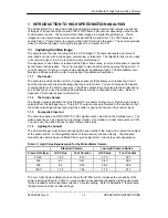
Страница 9: ...You must increase illumination to compensate for the shorter exposure The Strobe output is synchronized to the shutter timing so a strobe may be used to increase illumination as well as to eliminate motion blur Refer to Appendix C for shutter exposure information 1 1 2 The Strobe Output The Strobe output is available from the Digital Out connector during Live or Record mode when selected from the ...

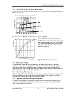
Страница 10: ...Filters are installed at the factory and cannot be changed in the field 1 2 1 The Imager Base Characteristics Figure 1 1 gives the responsivity and sensitivity of the TC237 monochrome CCD imager without a filter across the range of visible light to the near IR band Figure 1 1 The Spectral Characteristics of the TC237 Sensor 1 2 2 Spectral Response with a CM500 IR Filter Figure 1 2 shows the respon...

Страница 11: ... of application recording a specific event or viewing a continuous video until an event triggers an end to the sequence The elapsed recording time depends on the number of frames per second recorded and the number of frames that the memory can store Refer to Appendix A where the elapsed record time can be determined from the Record Rate and the capacity of the Image Memory 1 3 1 Recording a Video ...

Страница 12: ...lts The trigger causes a contact closure that pulls the trigger input down to 0 volts 2 A closed contact pulls the trigger input down to 0 volts The trigger opens the contact causing the trigger input to rise to 3 3 volts 3 The trigger input operates with TTL or CMOS logic as the trigger source The voltage from the source is pulled low by a resistor at the source up to 2K ohms in value The trigger...

Страница 13: ...1 4 Marking a Frame Event Marker The MotionMeter provides a means to identify a frame or series of frames in the recorded sequence This Event Marker feature when turned on places a square marker at the top left corner of each frame The Event Marker inputs are held high 3 3V TTL level and the marker shows as a black square on each frame A contact closure to ground pulls the input low and the marker...

Страница 14: ...using the manual stop A message shows on the screen between the time of receipt of the trigger signal and the time the camera stops recording to confirm that the trigger was received and to prevent the operator from pressing Stop manually Figure 1 9 The 0 Trigger 1 6 3 Playing Images from the Image Memory You can play back the images from memory as soon as the sequence is recorded The camera plays...

Страница 15: ...yback Playback at frame rates above 60 fps 50 fps PAL will cause the loss of frames displayed in the viewfinder and on computer displays This does not indicate a loss of video data All frames can be accessed at lower playback rates 1 7 2 Analyzing the Motion of a Subject The MotionMeter provides several features to examine a recorded sequence 1 Slow or Fast Motion You can replay the video sequence...

Страница 16: ...REDLAKE MASD INC _____________________________________________________________________________ 9400 0024 Rev G 1 8 05 15 01 This page intentionally left blank ...

Страница 17: ...losure has a 3 8 16 threaded hole in the bottom of the enclosure to mount the Camera Head onto a tripod All standard cameras have IR filters that give the subject an accurate grayscale rendering A model of camera without a filter is available for low light applications Refer to Paragraph 1 1 1 for the light value requirements for each of these models 2 2 1 MotionMeter Features and Functions The ca...

Страница 18: ... camera returns to Live mode when the Stop button is pressed 2 3 2 The PLAY Buttons Press a PLAY button momentarily to view a sequence of images from the Image Memory at the frame speed set forward or reverse The screen shows PLAY mode Press the or buttons to increase or decrease the number of frames displayed per second during playback by one step in the range In STEP mode each push of the PLAY b...

Страница 19: ...amera comes up in Live mode at power up and returns to Live mode when the Stop button is pressed during Record or Playback You can change the Record Rate Shutter setting and Trigger settings in Live Mode Figure 2 2 The Live Mode Screen To make changes go to LIVE mode using the MENU button select the parameter using the SEL button then use the and buttons to select the value from the range of value...

Страница 20: ...o see the Play mode screen and view the images stored in the buffer The camera plays the images at the F sec PLAY rate shown in the menu You can press the other Play button to view the images in the other direction without using the Stop button The F SEC RECORD menu indicates the number of frames recorded each second Frame rates are as follows Single Frame 1 2 3 4 5 10 25 PAL 30 NTSC 50 PAL 60 NTS...

Страница 21: ...D Bright This sets the brightness of the viewfinder This does not affect the Video Out signal NTSC PAL Sets the video standard output for the Video Out signal 2 5 Input and Output Connectors 2 5 1 Power The camera requires 12 volts DC at 2 Amps The power connector is a DIN 3 pin connector There is no Power ON OFF switch on the unit this function is located on the power cord 2 5 2 Digital in This i...

Страница 22: ... power supply output has an output cable and DIN plug for the camera The input cable has a standard IEC connector to the power supply The input cable can be replaced for alternative international power plug configurations 2 6 2 Battery Pack and Charger The rechargeable battery pack is a separate unit that plugs into the camera power input plug The sealed lead acid battery has a capacity of 2 4 Amp...

Страница 23: ...The camera outputs NTSC 30 fps or PAL 25 standard Use the Settings menu to change the video standard 3 1 4 The Event Marker Input The Event Marker input to the Digital In connector shows a white square when the input is 3 3 volts A contact closure to ground turns the marker black Select this input using the Settings menu Figure 3 1 The Event Marker Input Circuits There are two types of input that ...

Страница 24: ... or CMOS compatible logic signal or other ground based logic with a maximum of 2K ohms holds the Trigger input at 0 volts The Trigger signal allows the Trigger input to go to 3 3 volts to stop recording This signal can go as high as 30 volts You must set the arrow in the menu up Figure 3 3 Trigger Input Circuits 3 1 7 The Phase Lock Input and Output 1 Determine which camera will be the master and ...

Страница 25: ...more cameras can be synchronized to an equipment source If there is more than one Slave unit the connections can be series or parallel See Figure 1 6 and substitute the equipment source for the Master unit The Phase Lock signal level is 3 3 volts which must fall to 0 volts prior to the next frame exposure This signal s rising edge causes the start of a frame exposure See Figure 3 4 Figure 3 4 The ...

Страница 26: ...REDLAKE MASD INC _____________________________________________________________________________ 9400 0024 Rev G 3 4 05 15 01 This page intentionally left blank ...

Страница 27: ...h 4 1 1 above 4 2 1 2 Record Rate Select the Live mode menu The menu shows the current rate set and gives the range of values available to your camera model Press the or buttons to set a new record rate Refer to Appendix A for record times 4 2 1 3 Shutter The Live menu shows the current shutter speed Select the menu and press the or buttons to set a new shutter speed The menu shows the shutter spe...

Страница 28: ... not record without a signal to the Phase Lock In 4 5 Synchronizing Two or More Cameras Set the cameras up as described in paragraph 1 3 3 and follow the procedure given here 1 Determine which camera is the Master camera and which is are the Slave s 2 Connect the BNC cables and connectors as shown in Figure 1 6 3 Use the Menu Button to select the Settings Menu on each camera 4 Set the cameras to M...

Страница 29: ...depends on the operating environment Use a lens brush do NOT wipe the lens with a cloth or tissue 5 2 Troubleshooting 5 2 1 No Picture on the Viewfinder or Monitor 1 Lens cover on 2 Lens aperture closed 3 Insufficient illumination The camera requires very high illumination to operate at high speeds and short shutter settings 5 2 2 Video Channel Imbalance The video image is taken from two analog vi...

Страница 30: ...REDLAKE MASD INC _____________________________________________________________________________ 9400 0024 Rev G 5 2 05 15 01 This page intentionally left blank ...

Страница 31: ...mera Each model can record at all frame rates from 60 frames per second up to the maximum rate of the model used MotionMeter Resolution and Record Rates 64K 128K Memory Record Rate Resolution Standard Memory 64K Enhanced Memory 128K Frames Sec Pixels Record Time of Frames Record Time of Frames 50 PAL 292x220 20 5 Sec 1 024 41 0 Sec 2 048 60 NTSC 292x220 17 1 Sec 1 024 34 1 Sec 2 048 125 292x220 8 ...

Страница 32: ...dard Capacity 1 024 frames 2 048 at 1000fps Enhanced Capacity 2 048 frames 4 096 at 1000pfs Playback Mode Plays back in either direction at the selected rate when you press the Play buttons Playback Rates Single Step 1 2 3 4 5 10 25 PAL 30 NTSC 50 PAL 60 NTSC 125 250 500 and 1000 frames per second forward or reverse Status Display Record Rate Shutter Trigger Point Trig trigger actuated Event Frame...

Страница 33: ...3 volts up to 30 volts permitted 2 Contact closure rising to 3 3 volts when contact opens 3 Contact closure at 3 3 volts falling to 0 volts when the contact opens Size Power and Operating Environment Camera Dimensions 8 3 211mm wide x 5 5 140mm high x 2 5 64mm deep Weight 1 5 lb 0 7 kg without lens Power 12 volts DC 2 Amps Redlake supplies a Panasonic EB P0783B universal input voltage AC DC power ...

Страница 34: ...he maximum frame rate for each system For example a 1000 S has frame rates of 60 50 PAL 125 250 500 and 1000 fps Exposures vs Shutter Speeds and Record Rate Frames per Second Shutter Speed 50 60 125 1X 20 0 ms 17 00 ms 8 00 ms 2X 10 0 ms 8 30 ms 4 00 ms 3X 6 7 ms 5 60 ms 2 67 ms 4X 5 0 ms 4 20 ms 2 00 ms 5X 4 0 ms 3 30 ms 1 65 ms 10X 2 0 ms 1 70 ms 0 80 ms 20X 1 0 ms 0 83 ms 0 40 ms Shutter Speed ...

Страница 35: ...2000 0084 Power Cord Required with the 2000 0084 Power Supply 2000 0087 MotionMeter Battery Pack DC Option 2000 0088 MotionMeter Battery Pack Charger 2000 0103 USB Videobus Belkin F5U206 9083 0014 MotionMeter Camera Case 9033 0042 MotionMeter Camera and Accessory Case 9033 0048 Trigger Switch with 10 foot cable and BNC connector 1700 0001 C Mount Lenses 8 mm Lens f 1 3 DO Industries 9001 0389 12 5...

Страница 36: ...Lens Set 1 2 4 Cosmicar only 9002 0059 Tripods and Mounting Devices Tripod Bogen 3021 Stand and 3047 Head 9005 0059 Clamp Bogen 2915 9005 0060 Bogen variable friction arm with camera mount 9005 0061 Soft Bag for above 9005 0065 Tripod Bogen 3008 Stand and 3009 Head 9005 0070 Tripod Bogen 3021S Stand and 3030 Head 9005 0071 Monitors and VCRs Monitor Sony PVM 137 14 Monochrome with underscan 9017 00...

Отзывы: