


Removing and Installing a CF Card
Servicing the Hardware
6-7
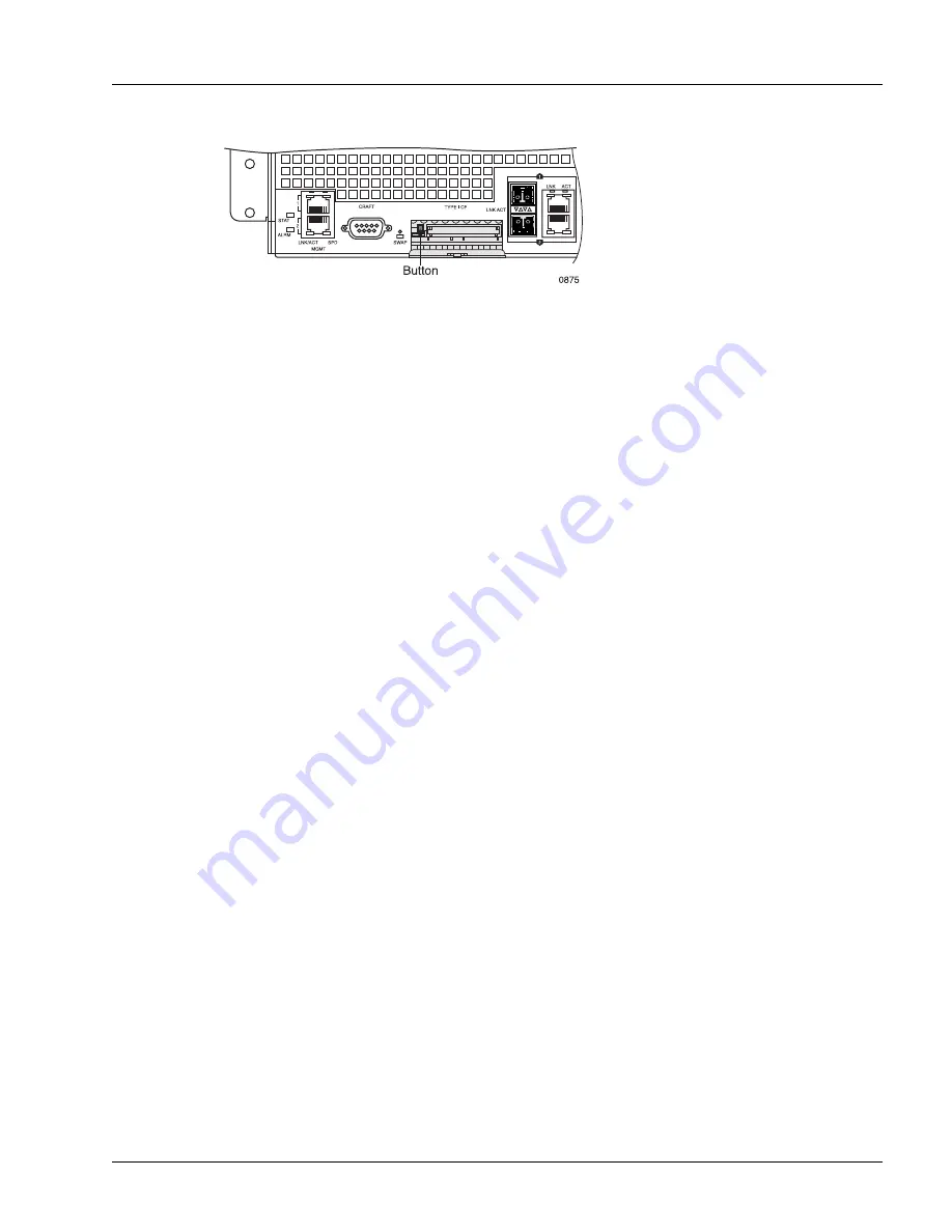
Figure 6-4
CF Card Ejection Button
Install a CF Card
To install a CF card, perform the following steps:
1. Put on an antistatic wrist strap (one is shipped with the system), and attach it to an appropriate grounded
surface.
2. If a CF card is currently installed, remove the card using the procedure described in the “Remove a CF
3. Hold the CF card to be installed so that its pin-hole side faces the slot in the front panel and horizontally
align it as close to the bottom edge of the slot as possible and perpendicular to it; see Figure 6-5.
4. Slowly insert the card in the slot; keep the card perpendicular to the front panel. If the card does not
engage the circuit board connectors with approximately 0.50 inches (1.27 cm) of the card outside the
slot, do not continue. Remove the card and repeat this step.
5. Close the door until it snaps shut. The system automatically recognizes the CF card and begins to mount
it. The SWAP LED begins to blink.
6. After the SWAP LED stops blinking (is off), you can begin using it to store data.
Note
Do not attach the wrist strap to a painted surface; there is an ESD convenience jack located on
the chassis front panel.
Note
The CF card is polarized; if the card does not engage the connectors, rotate the card 180° and
try again.
Note
If for some reason, the system cannot successfully mount the file system on the CF card (for
example, the file system is damaged or the card is unformatted), the SWAP LED stops blinking
and changes back to “Off” and the system displays an error message on the console. You must
enter the
format
microdrive
command (in exec mode) to format the CF card and the
mount
command (in exec mode) to mount it.
For more information about the
format
microdrive
and
mount
commands, see the “Hardware
Operations” chapter in the
Ports, Circuits, and Tunnels Operations Guide
for the
SmartEdge OS.
Содержание SmartEdge 100
Страница 4: ......
Страница 8: ...viii SmartEdge 100 Router Hardware Guide...
Страница 14: ...Ordering Documentation xiv SmartEdge 100 Router Hardware Guide...
Страница 52: ...Connecting and Routing the Cables 4 18 SmartEdge 100 Router Hardware Guide...
Страница 72: ...Obtaining Assistance 5 20 SmartEdge 100 Router Hardware Guide...
Страница 90: ...FE and GE MIC and Native Port Cables A 6 SmartEdge 100 Router Hardware Guide...
Страница 94: ...FE and GE Port Alarms B 4 SmartEdge 100 Router Hardware Guide...