background image

11

2 INSTALLATION

2.5 

Wiring

The heavy gauge wires on the BCDC1212T unit carry peak currents of up to 25 Amps, and it is important 
to make good, low resistance, electrical connections that will not degrade over time. Failure to make a 
good, reliable contact may result in breakdown of the wire insulation and cause a short circuit, or worst 
case a fire. We recommend that this activity be undertaken by an appropriately qualified or experienced 
person.

The BCDC1212T brown and black wires are fitted with 

3

/

16

"

 (M5) and 

5

16

"

 (M8) lugs respectively for ease 

of installation. It is recommended that the BCDC1212T be installed as close as possible to the auxiliary 
battery it is charging to minimize cable length and associated voltage drop. Ideally the brown wire should 
be connected to the fuse on the auxiliary battery (see Figures 2.7.1 and 2.7.2) without adding additional 
length to the brown wire. The BCDC1212T black wire should be connected to a good quality ground. It is 
important that all the ground connections of the start battery, auxiliary battery, between the tow vehicle 
and trailer, and the BCDC1212T be high quality, have a low impedance between them and be corrosion 
free. The red (input) wire can be connected directly to the trailer plug’s +12 V Auxiliary Power pin, 
provided that towing harnesses and connectors are suitably rated (see CAUTION in section 2.6)

2.6 

Fusing

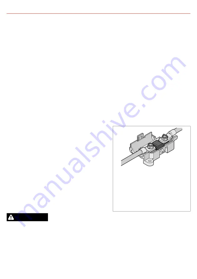
Fuses must be connected close to the start battery 
and the Auxiliary battery in order to protect the wiring 
and connectors between the batteries and the BCDC. 
REDARC recommends using MIDI style bolt down fuses 
as they ensure a low resistance connection. The REDARC 
FK23 and FK30 fuse kits are recommended. 

Blade type fuses are not recommended as they can 
result in a high resistance connection which causes 
excess heat and may damage the fuse holder and/or the 
wiring.

Self-resetting circuit breakers are not recommended as 
they may trip prematurely due to the heat generated by 
the current flowing through the wires.

A single fuse and holder setup from the 

Fuse Kits are available from REDARC.  

Part number FK23 (23 A) or FK30 (30 A).

CAUTION

In applications where the BCDC1212T draws power through the vehicle’s and trailer’s towing harnesses 
and connectors, the harnesses wiring gauge, connectors and fuse current ratings and fuse type should be 
checked by a suitably qualified person to ensure that it is adequately rated for safe and reliable operation 
and that the vehicle’s fuse is appropriately rated and located to protect the wiring in the event of a fault, 
including short circuits.

Содержание BCDC1212T

Страница 1: ...Multi stage 12 V Input Current Limited In vehicle Battery Charger BCDC1212T ...

Страница 2: ...er s data for your battery and ensure that the Continuous Current Rating of the charger does not exceed the manufacturer s recommended maximum charging current 6 When using the Battery Charger to charge a Lithium Iron Phosphate LiFePO4 battery only batteries that feature an inbuilt battery management system featuring inbuilt under and over voltage protection and cell balancing are suitable 7 The B...

Страница 3: ...10 5 V 32 F to 176 F 0 C to 80 C LiFePO4 Batteries 32 F to 176 F 0 C to 80 C Weight 30 oz 850 g Dimensions 6 5 4 7 1 5 165 120 37 mm Warranty 2 years EMC Compliance RCM FCC ICES Voltages Specified are 100 mV CONTENTS THE BCDC1212T 2 WARNING AND SAFETY INSTRUCTIONS 2 SPECIFICATIONS 3 1 PRODUCT FUNCTION 4 1 1 Display Panel 4 1 2 Charge Profile LEDs 4 1 3 Charge Status LEDs 5 1 3 1 Vehicle LED 5 1 3 ...

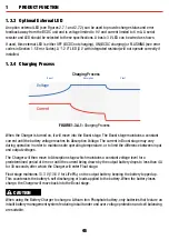
Страница 4: ... 20 A when connected to a 24 V alternator the peak boost current however also depends on alternator voltage and input cable voltage drop The BCDC1212T isolates the start battery from the auxiliary battery to avoid over discharging the start battery 1 1 Display Panel The front panel features 7 LEDs to display the charge profile and charge status Figure 1 1 1 The BCDC1212T Front Panel 1 2 Charge Pro...

Страница 5: ...he Vehicle LED will be ON when the input is available and in use and OFF when the input is not available or not in use 1 3 2 Stage LED The Stage LED indicates the charge profile stage With any profile selected the charger will output a 3 Stage charging profile consisting of Boost Absorption and Float Stages Figure 1 3 2 1 outlines the LED sequences which indicate these stages and figure 1 3 4 1 ex...

Страница 6: ...nt until the battery voltage reaches its Absorption Voltage The current in Boost stage may vary during operation in order to maintain safe operating temperature or to limit the difference between input and output voltages The Charger will then move to Absorption stage which maintains a constant voltage level for a predetermined period of time or until the current being drawn by the output battery ...

Страница 7: ...is a maximum 20 second delay before the charger will produce an output any time a source is introduced into the system this allows the unit to provide optimum input sharing and effective battery isolation 1 5 Error Codes In the event of a fault with the unit installation or either battery ALL the LEDs on the unit will flash to indicate the fault type Flashing sequences are described in the table b...

Страница 8: ...eas for maximum performance Choose locations such as on the inner guard behind a headlight or behind the grille to one side of the radiator The unit will operate optimally below 130 F 55 C with good airflow At higher temperatures the unit will de rate output current up to 176 F 80 C at which point the unit will turn OFF It is important to ensure the charger is mounted as close as possible to the b...

Страница 9: ... Input source positive This will set the Maximum voltage to 15 3 V To select the Li Profile connect the ORANGE wire to the GREEN wire LED output This will set the charger to Lithium mode CAUTION Check the manufacturer s data for your battery and ensure that the Maximum voltage of the profile you select does not exceed the manufacturer s recommended maximum charging voltage If the Maximum voltage i...

Страница 10: ...n some applications the BCDC could deplete the start battery to 11 9 V 100 mV or 23 8 V 100 mV for 12 V and 24 V vehicles respectively 2 4 Cable sizing Below is a table outlining the required cable size for a given cable install length Please refer to this table for Vehicle Input Ground and Battery Output cable thickness requirements Always choose a wire cross sectional area equal to or greater th...

Страница 11: ...e red input wire can be connected directly to the trailer plug s 12 V Auxiliary Power pin provided that towing harnesses and connectors are suitably rated see CAUTION in section 2 6 2 6 Fusing Fuses must be connected close to the start battery and the Auxiliary battery in order to protect the wiring and connectors between the batteries and the BCDC REDARC recommends using MIDI style bolt down fuse...

Страница 12: ...ttings Leave unconnected 12V or 24V Start Battery Bank Fuse Ratings as per table on Page 3 12V or 24V Start Battery Bank Fuse 24V INPUT Fuse Optional LED All ground points must be connected to chassis earth Auxiliary Battery Charging Profile Select Refer to section 2 2 Red Blue Orange Black Brown Green 12V INPUT OR INPUT Standard Trigger Settings Low Voltage Trigger Settings Load Fuse Loads to Veh...

Страница 13: ...iary battery is above 0 1V 4 Check all wiring to the Auxiliary battery particularly the Ground BLACK wire 5 Check fuses are intact and properly connected If the problem is still evident please see the relevant points below THE BCDC IS CONNECTED TO THE VEHICLE BUT THE VEHICLE LED IS OFF This indicates that the required turn ON conditions for this source have not been met With the BLUE wire left unc...

Страница 14: ...can operate from a voltage of above equal to or below the desired output voltage The unit is also microprocessor controlled allowing it to output a REDARC proprietary charging algorithm independent of the input This allows the unit to charge specific to the battery type even if the input voltage is low due to voltage drop Q Where should I mount the BCDC Unit A The BCDC should be mounted as close a...

Страница 15: ...to reject any Warranty claim made by a Purchaser pursuant to this Warranty where 11 1 the Purchaser does not notify REDARC in writing of a Warranty claim within the Warranty Period 11 2 the Purchaser does not notify REDARC in writing of a Warranty claim within 1 month of becoming aware of the relevant circumstances giving rise to the claim so that any further problems with the Product are minimize...

Страница 16: ... to Friday or send us an e mail INST55 5 EN Australia and other Global regions power redarc com au www redarc com au 61 8 8322 4848 New Zealand power redarcelectronics co nz www redarcelectronics co nz 64 9 222 1024 North America power redarcelectronics com www redarcelectronics com United States 1 704 247 5150 Canada 1 604 260 5512 Mexico 52 558 526 2898 UK Europe power redarcelectronics eu www r...

Отзывы: