background image

DO NOT operate or store near any heat sources such as 
radiators, heat registers, stoves, or any other apparatus that 
produce heat. Store in a protected, level and ventilated place. 
Avoid exposure to temperature extremes, damp, severe vibration, 
strong magnetic fields, direct sunlight or local heat sources during 
storage. Remove any batteries from the camera before storage. 
Recommended storage and usage temperatures for your camera, 
lenses and other accessories are:

Operating range: 0°C to 40°C (32°F to 104°F)

Storage range: –20°C to 50°C (–4°F to 122°F)

If there are any performance issues with your camera or 
accessories when operating within this temperature range, submit 
a Support ticket at 

https://support.red.com

.

Lens mounts are NOT HOT SWAPPABLE, meaning you cannot 
remove or install these items while the camera is turned on. 
Before installing or removing these items, you MUST turn off the 
camera. Failure to do so may result in damage to the item or 
camera that is not covered under warranty.

DO NOT bypass the third prong of the grounding-type plug on the 
power cord of the included power adaptor. A grounding-type plug 
has two blades and a third “grounding” prong. The third prong is 
provided for your safety. A grounding-type plug shall be connected 
to an outlet with a protective earthen connection. If the grounding-
type plug does not fit into your outlet, do not attempt to modify the 
plug or outlet, consult a qualified electrician.

Protect all power cords from being pinched, walked on or driven 
over by a vehicle. Replace any power cords suspected of 
sustaining damage due to crushing or other forms physical 
damage.

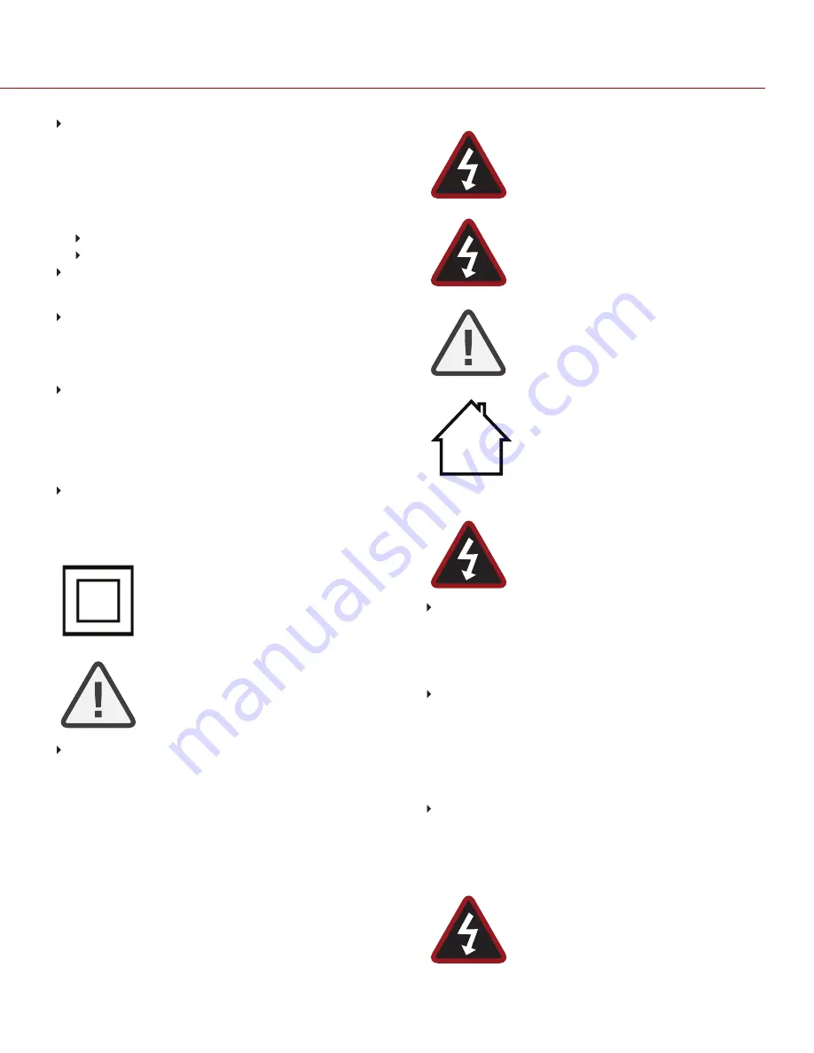
Products   marked   with   this   symbol   are   class   2  
devices.   These   devices  are   not   provided   with   a  
grounding type plug.

CAUTION: The power  cord plug for  the included 
power   adaptor   is  used  as  the  power   disconnect. 
To disconnect all power  from the power  adaptor, 
unplug the power  cord plug from the wall outlet. 
During   use,   the   power   cord   plug   should   remain  
easily accessible at all times.

Lithium-ion batteries may be subject to special handling 
requirements pursuant to federal and local laws. Refer to specific 
shipping instructions included with your battery regarding proper 
transport of your battery. Do not handle your battery if it is 
damaged or leaking. Disposal of batteries must be in accordance 
with local environmental regulations. For example, California law 
requires that all rechargeable batteries must be recycled by an 
authorized recycle center. Storing batteries fully charged or in high 
temperature conditions may permanently reduce the life of the 
battery. Available battery capacity may also be temporarily 
lessened after storage in low temperature conditions.

C OPYR I GH T © 2 0 2 0 R ED . C OM , L L C

9 5 5 - 0 1 9 2 _ V7 . 3 , R EV- A   

|

   6

RED RANGER GEMINI OPERATION GUIDE

WARNING:   DO   NOT   expose   the   battery   to  
excessive heat.

WARNING:   Danger   of   explosion   if   an   incorrect  
battery  is  charged   with   the   RED   Charger   or   is 
used   to   power   the   camera   and   accessories.  
Replace   only   with   the   same   or   equivalent   type  
battery.

CAUTION: Refer all service and repair to qualified 
RED   service   personnel.   To   reduce   the   risk   of  
electric   shock,   and   damage   to   the   camera   or  
accessories,   DO   NOT   attempt   to   perform   any  
servicing   other   than   any   procedures   that   are  
recommended in the operating instructions.

INDOOR   USE   ONLY:   This  device   is  designed  
for use indoors only.

BATTERY STORAGE AND HANDLING

WARNING:   Failure   to   read,   understand,   and  
follow these instructions may result in overheating, 
chemical  leakage,  smoke  emission,  fire,  or   other  
potentially harmful results.

Always follow proper battery handling and storage practices. 
Improper handling and/or failure to abide by proper storage 
instructions may cause permanent damage to batteries, or 
degrade battery charge holding capacity. Improper handling 
practices or failure to comply with instructions may also put you at 
risk.

Lithium-Ion batteries, like the REDVOLT

®

, REDVOLT-V, 

REDVOLT XL, and RED BRICK

®

, self-discharge over time. When 

storing for long periods of time, store batteries separately from the 
camera or charger and remember to charge batteries to a 
capacity level of 40% to 60%. If batteries will be stored for long 
periods of time, RED recommends that you check the charge level 
at least once every six (6) months, and recharge batteries to a 
capacity level of 40% to 60%.

When not in use, remove the battery from the camera or charger 
and store the battery in a cool, dry place. Avoid extreme hot 
temperatures (such as inside a hot car), corrosive gas, and direct 
sunlight. The optimal storage temperature for batteries is between 
–20°C to 20°C (–4°F to 68°F).

WARNING: Batteries stored in a discharged state 
for   long   periods  of   time   may  self- discharge   and  
lose the ability to hold a charge.

Содержание RANGER GEMINI 5K S35

Страница 1: ...GEMINI 5K S35 V7 3 RED COM RED RANGER GEMINI OPERATION GUIDE...

Страница 2: ...e Action Area 42 Lower Status Row 43 CHAPTER 5 Sensor Calibration 49 When to Calibrate Sensor 49 Calibrate Sensor Manual Calibration 50 Calibrate Sensor Auto Calibration 52 Calibration Map Naming Conv...

Страница 3: ...egistered trademark of Acument Intellectual Properties LLC in the United States or other countries IOS is a registered trademark of Cisco in the U S and other countries Avid is a registered trademark...

Страница 4: ...for radio equipment RED declares digital devices described in this document comply with the following Australian and New Zealand standards AS NZS CISPR 32 Electromagnetic Compatibility AS NZS 61000 3...

Страница 5: ...the unit as well as electric shock and serious injury to the user DO NOT use the camera in the rain or under other conditions with high moisture without appropriate protection and immediately remove...

Страница 6: ...ged or leaking Disposal of batteries must be in accordance with local environmental regulations For example California law requires that all rechargeable batteries must be recycled by an authorized re...

Страница 7: ...F RED recommends that you only use RED chargers to recharge RED batteries Store the battery in a location where children cannot reach it If the battery leaks or gives off a bad odor discontinue use im...

Страница 8: ...allenging shooting environments RED RANGER GEMINI is capable of handling the rigorous strain and robust power needs of high end studio productions RED RANGER GEMINI supports wide input voltage 11 5V t...

Страница 9: ...loads to download the latest firmware operation guides and post production software DSMC Toolkit Go to RED Downloads to find the DSMC Toolkit which offers many helpful tools and resources to customize...

Страница 10: ...these items you MUST turn off the camera Failure to do so may result in damage to the item or camera that is not covered under warranty NOTE Availability of components listed in this chapter is subje...

Страница 11: ...o to Record and Monitor Audio 3 Mic 2 Right audio channels Ch2 and Ch4 Go to Record and Monitor Audio 4 User Key 2 Programmable key User Key 1 2 Press Eject Media 5 REC Button Programmable key Full Pr...

Страница 12: ...EVF Adaptor D 8 Top Handle Port Mount the DSMC2 Top Handle or DSMC2 Outrigger Handle This is the only mounting option for the DSMC2 Top Handle or DSMC2 Outrigger Handle it cannot be attached backward...

Страница 13: ...ndard rosette Features an M6 threaded hole in the center use with cages or accessories that feature rosette based mounting systems 12 Focal plane marks Marks align with the sensor plane pull focus fro...

Страница 14: ...t a DSMC2 RED Touch LCD or LCD EVF Adaptor D The secondary LCD EVF port and a MON 1 port cannot be used at the same time Go to Monitor Preferences 18 Hook and loop patch Rectangle of hook and loop mat...

Страница 15: ...Battery mount Depending on the RED RANGER type you can attach either a gold mount battery or a v lock battery 20 Media mount Mount RED MINI MAG media 21 Fan exhaust DO NOT block fan exhaust when the c...

Страница 16: ...tures ITEM LOCATION DESCRIPTION 21 Fan exhaust Back Bottom DO NOT block fan exhaust when the camera is on 22 Mounting Points Bottom Mount plates tripods monopods etc COPYRIGHT 2020 RED COM LLC 955 019...

Страница 17: ...y time available Red Camera shutting down Record Status LED REC Off No media present Green Ready to record Amber Finalizing Red flashing slow Media mounted 5 and 10 of media available Red flashing fas...

Страница 18: ...10 of media space available Amber Record finalizing or playback mode Amber flashing slow Formatting media Red flashing slow Media mounted 5 and 10 of media available Red flashing fast Media mounted 5...

Страница 19: ...Status LED1 Off Not recording or media not mounted Red Recording 1 For more information on how to enable disable this LED go to Indicator If media is not mounted this LED is off COPYRIGHT 2020 RED CO...

Страница 20: ...offers the following RED MINI MAG SSDs ITEM PART NUMBER RED MINI MAG 120GB 750 0075 RED MINI MAG 240GB 750 0082 RED MINI MAG 480GB 750 0090 RED MINI MAG 512GB V41 750 0078 RED MINI MAG 512GB V51 750...

Страница 21: ...0002 For use with V Lock RED RANGER AC Power Adaptor 270W 740 0048 Power adaptor for AC power 3 pin female XLR 3 PIN XLR TO 4 PIN 2B POWER CABLE 10 790 0665 Connects the DC IN port to the RED RANGER...

Страница 22: ...RANGER to a 16 Pin 1B LCD EVF port The DSMC2 LCD EVF Adaptor A is designed to attach to the primary top EVF LCD port on the RED RANGER When used along with the DSMC2 LCD EVF Adaptor B this adaptor en...

Страница 23: ...gned to attach to the primary top or the secondary side EVF LCD port on the RED RANGER When used along with the DSMC2 LCD EVF Adaptor B this adaptor enables you to mount a DSMC2 RED Touch LCD away fro...

Страница 24: ...Top Handle offers the ideal handle and shooting method for your camera DSMC2 OUTRIGGER HANDLE Figure DSMC2 Outrigger Handle The DSMC2 Outrigger Handle offers a low profile side handle designed with a...

Страница 25: ...interchangeable optical low pass filters OLPFs The camera automatically recognizes the OLPF type installed eliminating the need to configure OLPF settings in the camera menu RED offers the following...

Страница 26: ...hed directly to the camera body 30 lbs Production Handle 105 2120 One riser attached to a plate handle extension attached 40 lbs Two risers attached to a plate handle extension attached 80 lbs PRODUCT...

Страница 27: ...ces are connected to the camera power consumption is prioritized in this sequence 1 Any power supply connected to the DC IN port 2 Rear battery POWER CONSUMPTION The camera draws approximately 4 2 A 6...

Страница 28: ...s the camera turns on The Power Status LED illuminates green to confirm that the camera is turned on and ready to use TURN OFF THE CAMERA Use one of the following methods to turn off the camera Go to...

Страница 29: ...ector on the bottom of the handle with the connector on top of the camera 3 Tighten the two 2 captive screws approximately two 2 turns each using a 3 16 hex key DO NOT FULLY TIGHTEN 4 Fully tighten th...

Страница 30: ...attach the measuring tape to the hook To install the focus hook screw follow the instructions below REQUIRED TOOL S Slotted screwdriver 1 Remove the focus hook screw from the Focus Hook Screw Storage...

Страница 31: ...0 0020 125 4660 005 75 0030 SHIM OFFSET STACK TABLE The table below shows the offsets as measured in microns created by using different combinations of shims Shimming requires no more than one 1 of ea...

Страница 32: ...ring assembly Add the thinnest shims first and then add the thicker ones so that the thicker shims hold the thinner shims in place Figure Shim Installation 5 Place the lock ring assembly back onto th...

Страница 33: ...T20 TORX driver to turn the OLPF lock on the camera counter clockwise by a third turn to the Unlock position DO NOT turn the indicator mark past the Unlock icon WARNING DO NOT OVERTIGHTEN 7 Remove the...

Страница 34: ...for any damage caused by using a tripod monopod mount or support system that does not provide sufficient support WARNING DO NOT use excessive force to mount a support accessory as this may damage the...

Страница 35: ...an external VTR or DDR device It may be configured for 10 bit LIN VIDEO or 10 bit LOG FILM encoded data VIDEO MONITOR CATEGORIES Video monitor outputs are separated into three 3 categories VIEWFINDER...

Страница 36: ...d simultaneously follow the instructions below 1 Connect the camera to an external recorder with an HD SDI cable 2 Ensure that a formatted SSD is inserted in the camera 3 Set up the HD SDI output A Go...

Страница 37: ...erwise the external recorder records the overlay C Select the output resolution from the Resolution drop down menu NOTE The HD SDI maximum resolution is 1080p For more information go to Record Monitor...

Страница 38: ...camera information Functionality varies based on monitor output type and firmware version The GUI menu is organized in the following way By three 3 sections Figure GUI Control Menu ITEM DESCRIPTION 1...

Страница 39: ...cording frame rate Frame Rate 2 ISO Camera sensitivity ISO 3 Aperture Lens aperture F stop information Aperture on page 41 4 Exposure Shutter Integration time or shutter angle Exposure Shutter 5 Color...

Страница 40: ...enu in the Advanced Menus For example select Advanced in the Frame Rate menu to open Menu Settings Project Frame Rate For more information about Advanced Menus go Advanced Menus Figure Select Advanced...

Страница 41: ...uipped with Cooke S4 i system is attached Select the Advanced button to access the Menu Settings Setup Lens screen For more information go to Lens REDCODE Select the target REDCODE compression ratio f...

Страница 42: ...us Guide Crosshair Center of selected guide Reference guides Safe Action Safe Title Picture Center Grid Overlay General Tab 4 Frame Guides Record or sensor projection area Guides 5 Clip Filename Filen...

Страница 43: ...on HDRX Menu False Color Mode Displays modes False Color Modes Magnify mode Display Modes Magnify Timecode TC Indicator on page 47 Genlock GEN Indicator on page 47 Sync SYNC Indicator on page 47 RM RM...

Страница 44: ...ion Mode below Stills Mode on the next page Playback Menu MOTION MODE Motion mode optimizes your camera settings for capturing motion This mode defaults the camera to Continuous Record Motion mode inc...

Страница 45: ...llowing features Stills recording modes Multi Shot Motion Stills Swipe Up Shortcuts False Color Status Media Power Auto Focus Auto Exposure Record Mode Default Stills Preset RED For more information g...

Страница 46: ...d by White Balance ISO and VIEW LOOK settings 4 RAW Clip Meter Also known as traffic lights Provides a visual representation of exposure and sensor data levels for red green and blue channels Circles...

Страница 47: ...ignal cannot cross lock to project 24 00 fps vs 23 98 fps Red During process of sync or genlock is lost while recording Green A genlock signal matching the current HD SDI monitor rate is locked Yellow...

Страница 48: ...wering the camera via DC power the current voltage displays When powering the camera using batteries the remaining battery capacity displays The remaining capacity is indicated by the following colors...

Страница 49: ...anual Calibration for the HELIUM 8K S35 MONSTRO 8K VV and GEMINI 5K S35 sensors For more information go to Calibrate Sensor Manual Calibration on the next page Auto Calibration For more information go...

Страница 50: ...re to the exposure that you want to use for your shoot 3 Ensure that the sensor is as dark as possible Preferably take off the lens and install the front body cap If you cannot take off the lens put a...

Страница 51: ...gh the following phases of the calibration Capturing Analyzing Erasing Programming 9 When the Calibration Successful dialog displays select OK to complete the process The new calibration map is automa...

Страница 52: ...d to re calibrate the sensor after extreme changes in temperature This process can take up to 1 hour AUTO CALIBRATION PROCEDURE To perform an Auto Calibration follow the instructions below 1 Ensure th...

Страница 53: ...gure Select Sensor Sensitivity for Auto Calibration 6 Select OK on the dialog box that opens The system initializes and then makes multiple passes through the calibration phases 7 When the Calibration...

Страница 54: ...nth Month that the calibration map is created mm 01 Day Day that the calibration map is created dd 28 Letters Two random alphanumeric characters generated by the camera to prevent any possibility of d...

Страница 55: ...with Low Light For more information on Sensor Sensitivity go to Sensor Sensitivity Create Create a calibration map For more information go to Calibrate Sensor Manual Calibration on page 50 and Calibr...

Страница 56: ...nd the most recent version available online NOTE You must calibrate the sensor after upgrading the camera For more information go to Sensor Calibration on page 49 NOTE Preset Look and Custom Overlay f...

Страница 57: ...RED devices During this time the PWR and REC LEDs flash green and nothing displays on the external monitors 11 If this is your first time upgrading firmware a pop up menu opens with the Software Licen...

Страница 58: ...ARNING Use caution with compressed air and gas dusters since the high pressure oily residue cold air particulates and moisture may cause damage You may use a filtered non residue gas duster to clean n...

Страница 59: ...TED EVF SCREEN CLEANERS DO NOT use any of the items listed below to clean the screen on the DSMC2 RED EVF These products have not been tested on RED products and may cause damage or streaking Compress...

Страница 60: ...party cleaning kits Pre packaged lens cleaner containing any additives such as detergent anti static compounds or fragrance WARNING Damage to any screens or other components of the camera system cause...

Страница 61: ...r Test Pattern 4 Select the desired resolution 5 Select the highest available frame rate 6 Perform a secure format of the SSD 7 Record a full SSD of footage 8 Perform a secure format of the SSD 9 Repe...

Страница 62: ...Perform a Hardware Rediscover For more information go to Rediscover Hardware Rediscover CAMERA DISPLAYS N A FOR APERTURE SYMPTOM The camera displays N A for aperture when a lens is attached POTENTIAL...

Страница 63: ...jitter to the image on the monitor The jitter characteristic only displays in live preview and does not affect recorded footage For more information on sensor calibration go to Sensor Calibration on...

Страница 64: ...th REDCINE X PRO installed RED Watchdog mounts the SSD as Read Only by default which means that you are unable to write files including firmware upgrade files to the SSD Change the Mount preference to...

Страница 65: ...overexposed or underexposed Use the lowest REDCODE compression possible for the settings you have selected Use a higher resolution Use Adaptive fan mode to regulate the camera temperature Noise occurs...

Страница 66: ...t a Technical Support request at https support red com POSSIBLE HOT PIXEL SYMPTOM Your camera displays a possible hot pixel EXPLANATION There may not be an issue with the pixel itself The sensor can d...

Страница 67: ...e time For more information go to Monitor Preferences POTENTIAL RESOLUTIONS If an LCD or EVF is connected to the secondary LCD EVF port on the side of the camera remove the LCD or EVF Ensure that HD S...

Страница 68: ...when the error occurred include battery types power devices and power cables PRESET COULD NOT BE APPLIED SYMPTOM The display shows the following message Preset Could Not Be Applied POTENTIAL RESOLUTIO...

Страница 69: ...st Log file For more information go to Save Log List of devices lens and third party accessories that were attached when the error occurred Method for powering the camera when the error occurred inclu...

Страница 70: ...Calibration on page 49 Go to Menu Settings Maintenance Calibrate and select user1 Calibration Map Click Set Go to Menu Settings Maintenance Calibrate and delete all user created calibration maps Then...

Страница 71: ...d File Format Submit a Support ticket at https support red com Include the following with the request Log file For more information go to Save Log List of devices lens and third party accessories that...

Страница 72: ...layback Frame Rates Project Time Base 23 98 24 25 29 97 30 47 95 48 50 59 94 60 fps all resolutions Best Available REDCODE Settings1 3 1 REDCODE at 5K Full Height 5120 x 3000 and 24 fps 6 1 REDCODE at...

Страница 73: ...or 4 2 2 720p RGB or 4 2 2 SMPTE Timecode HANC Metadata 24 bit 48 kHz Audio Monitor Options DSMC2 Touch 7 0 Ultra Brite LCD Direct Mount DSMC2 RED Touch 4 7 LCD DSMC2 RED Touch 7 0 LCD and DSMC2 RED E...

Страница 74: ...0192_V7 3 REV A 74 RED RANGER GEMINI OPERATION GUIDE APPENDIX B MECHANICAL DRAWINGS RED RANGER GEMINI WITH V LOCK NOTE Dimensions are shown in mm The optical axis height of the camera is 95 90 mm FRON...

Страница 75: ...BACK VIEW Figure Camera Back View COPYRIGHT 2020 RED COM LLC 955 0192_V7 3 REV A 75 RED RANGER GEMINI OPERATION GUIDE...

Страница 76: ...SIDE VIEW RIGHT Figure Camera Side View Right COPYRIGHT 2020 RED COM LLC 955 0192_V7 3 REV A 76 RED RANGER GEMINI OPERATION GUIDE...

Страница 77: ...SIDE VIEW LEFT Figure Camera Side View Left COPYRIGHT 2020 RED COM LLC 955 0192_V7 3 REV A 77 RED RANGER GEMINI OPERATION GUIDE...

Страница 78: ...TOP VIEW Figure Camera Top View COPYRIGHT 2020 RED COM LLC 955 0192_V7 3 REV A 78 RED RANGER GEMINI OPERATION GUIDE...

Страница 79: ...BOTTOM VIEW Figure Camera Bottom View COPYRIGHT 2020 RED COM LLC 955 0192_V7 3 REV A 79 RED RANGER GEMINI OPERATION GUIDE...

Страница 80: ...WITH GOLD MOUNT NOTE Dimensions are shown in mm The optical axis height of the camera is 95 90 mm FRONT VIEW Figure Camera Front View COPYRIGHT 2020 RED COM LLC 955 0192_V7 3 REV A 80 RED RANGER GEMIN...

Страница 81: ...BACK VIEW Figure Camera Back View COPYRIGHT 2020 RED COM LLC 955 0192_V7 3 REV A 81 RED RANGER GEMINI OPERATION GUIDE...

Страница 82: ...SIDE VIEW RIGHT Figure Camera Side View Right COPYRIGHT 2020 RED COM LLC 955 0192_V7 3 REV A 82 RED RANGER GEMINI OPERATION GUIDE...

Страница 83: ...SIDE VIEW LEFT Figure Camera Side View Left COPYRIGHT 2020 RED COM LLC 955 0192_V7 3 REV A 83 RED RANGER GEMINI OPERATION GUIDE...

Страница 84: ...TOP VIEW Figure Camera Top View COPYRIGHT 2020 RED COM LLC 955 0192_V7 3 REV A 84 RED RANGER GEMINI OPERATION GUIDE...

Страница 85: ...BOTTOM VIEW Figure Camera Bottom View COPYRIGHT 2020 RED COM LLC 955 0192_V7 3 REV A 85 RED RANGER GEMINI OPERATION GUIDE...

Страница 86: ...ens mounts or camera that is not covered under warranty REMOVE A LENS MOUNT NOTE You can change lens mounts in the field However RED recommends that you change lens mounts only in a dust free environm...

Страница 87: ...slightly counter clockwise so that you can access the lens mount screws 5 Replace and loosely tighten the four 4 M4x0 7 x 8 mm lens mount screws in a cross pattern X pattern using a T20 TORX driver WA...

Страница 88: ...er s instructions This section also lists lenses supported by the camera PL mounts WARNING ALWAYS protect your equipment when it is not in use by replacing lens caps and mount caps ATTACH PL LENSES 1...

Страница 89: ...a Communication switch to On 4 On the lens set the LDS i Select switch to Off 5 Connect an external power source to the lens 6 In the camera to Menu Settings Setup Lens 7 Deselect the Enable Power to...

Отзывы: