


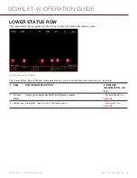

INTERCHANGEABLE OLPF SYSTEM
This section describes the process for swapping an interchangeable OLPF.
WARNING:
Read these instructions carefully and in their entirety before removing or installing an interchangeable
OLPF. Damage caused to the OLPF module, camera, or sensor due to improper handling or use is not covered under
warranty.
WARNING:
Once an interchangeable OLPF is removed from the camera, the sensor is exposed. Improper handling of
the OLPF modules or camera during this procedure may compromise the installation or cause irreparable damage to
your camera or sensor.
WARNING:
DO NOT allow any dirt or debris to enter the optical cavity.
WARNING:
Use only DSMC2 OLPFs. DO NOT use DSMC OLPFs. For any questions about OLPF compatibility,
please contact your Bomb Squad representative.
SWAP AN INTERCHANGEABLE OLPF
REQUIRED TOOLS:
T20 TORX driver
1. Turn off the camera.
2. Remove any modules, cables, or other accessories that may interfere with operations.
3. Loosen and remove the four (4) M4x0.7 x 8 mm lens mount screws in a cross pattern (“X” pattern) using a T20
TORX driver.
NOTE:
The DSMC Mg PL Mount 2.0 has captive screws that are not removable from the mount.
NOTE:
Screw removal may require a large handle T20 TORX driver and additional leverage.
4. Remove the lens mount.
5. Use a damp, lint-free cloth to gently wipe down the area around the lens mount and OLPF module. Remove as
much dust and debris as possible.
6. Use a T20 TORX driver to turn the OLPF lock on the camera counter-clockwise by a third turn to the Unlock
position. DO NOT turn the indicator mark past the Unlock icon.
WARNING:
DO NOT OVERTIGHTEN.
7. Remove the OLPF module and place it in its protective case.
8. Use an LED light to ensure that the optical cavity is clean and free from dust or debris.
9. Ensure the new OLPF module is clean and free of debris.
10. Install the new OLPF module straight into the optical cavity, keeping the front face of the OLPF module parallel to
the front of the camera.
NOTE:
Inserting the OLPF module at an angle may cause it to not seat properly.
11. Use a T20 TORX driver to turn the OLPF lock on the camera clockwise by a third turn to the Lock position. DO
NOT turn the indicator mark past the Lock icon.
WARNING:
DO NOT OVERTIGHTEN.
NOTE:
If the lock does not turn easily, gently press down on the OLPF module while turning the lock.
12. Replace the lens mount.
13. Replace and loosely tighten the four (4) M4x0.7 x 8 mm lens mount screws in a cross pattern (“X” pattern) using a
T20 TORX driver. DO NOT FULLY TIGHTEN.
NOTE:
The DSMC Mg PL Mount 2.0 has captive screws that are not removable from the mount.
14. Fully tighten the four (4) lens mount screws in a cross pattern (“X” pattern) using a T20 TORX driver. DO NOT
C O PYR I G HT © 2 0 1 6 R ED.C O M , I NC
9 5 5 - 0 1 3 3 _V 6 .3 , R EV - H
|
4 7
SCARLET-W OPERATION GUIDE
Содержание SCARLET-W
Страница 1: ...SCARLET W RED DRAGON MONOCHROME V6 3 RED COM SCARLET W OPERATION GUIDE ...
Страница 201: ...FRONT VIEW Figure SCARLET W Front View COPYRIGHT 2016 RED COM INC 955 0133_V6 3 REV H 201 SCARLET W OPERATION GUIDE ...
Страница 202: ...BACK VIEW Figure SCARLET W Back View COPYRIGHT 2016 RED COM INC 955 0133_V6 3 REV H 202 SCARLET W OPERATION GUIDE ...