28
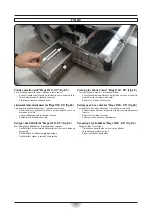
Montaggio e regolazione del tergipavimento
Per esigenze d’imballaggio il tergipavimento potrebbe venir fornito smon-
tato dalla macchina e dovrà essere applicato alla piastra di traino
sulla lavasciuga.
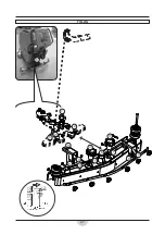
Per il montaggio del tergipavimento procedere nel seguente modo:
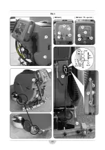
- posizionare i centraggi 1 in corrispondenza delle asole 2.
- mediante i pomelli 3, stringere il tergipavimento 4 alla piastra 5.
- montare il tubo aspirazione 6 sul tergipavimento.
Per una perfetta asciugatura del pavimento é essenziale che il tergipavi-
mento venga perfettamente regolato. La lavasciuga utilizza un tergipavi-
mento tipo “
V
”, come si vede in
fi
g.2/a.
Questo tipo di tergipavimento ha la caratteristica di raccogliere bene l’ac-
qua verso il tubo di aspirazione, peró é sensibile al parallelismo col terreno.
Per un buon funzionamento del tergipavimento bisogna cercare l’angolo
di lavoro ideale rispetto al pavimento. La gomma posteriore “A” del tergi-
pavimento deve lavorare il più verticale possibile e sul suo spigolo, come
si vede dalla
fi
gura, così che i liquidi vengano raccolti dal lato anteriore
della gomma.
Per ottenere ciò agire nel seguente modo:
- regolare il pomello 7 ruotandolo in senso orario (avvitare) per au-
mentare l’inclinazione del tergipavimento o in senso antiorario (svi-
tare) per diminuire l’inclinazione.
In funzione dei diversi tipi di pavimento da asciugare e dall’usura delle
gomme del tergipavimento bisogna regolare la sua altezza da terra, per
far ciò agire nel seguente modo:
- allentare le viti 8.
- agire sulle ruotine 9 per regolare l’altezza del tergipavimento e/o re-
golare il carico dello stesso sul pavimento.
Le stesse viti servono anche per regolare il tergipavimento in modo tale
che lavori parallelamente al pavimento.
Per una buona durata delle gomme, la pressione deve essere la minima
indispensabile, pur ottenendo una buona asciugatura.
Fare attenzione al fatto che, spesso, l’asciugatura viene in
fl
uenzata negati-
vamente da un cattivo funzionamento dell’aspirazione, in questo
caso:
- pulire perfettamente le tubazioni di aspirazione, gli ingressi, i
fi
ltri ed
il tergipavimento stesso.
- controllare il funzionamento del motore aspirazione.
- controllare che tutte le aperture d’ispezione del serbatoio siano ben
chiuse.
PREPARAZIONE DELLA MACCHINA (FIG.2/A)
Fitting and adjusting the squeegee
To suit packaging requirements, the squeegee may be supplied dismantled
from the machine, in which case it must be
fi
tted on the drive plate on the
scrubber-drier.
To
fi
t the squeegee, proceed as follows:
- set the centering holes 1 under the slots 2.
- by knobs 3
fi
t the squeegee 4 on the plate 5.
-
fi
t the vacuum hose 6 on squeegee.
For perfect
fl
oor drying, the squeegee must be properly adjusted.
fl
oor-
washer uses a V-shaped squeegee as shown in
fi
g. 2/a.
This type of squeegee conveys the water effectively towards the suction
pipe, but it must be parallel to the
fl
oor.
For good squeegee operation, it is important to set the ideal working angle
in relation to the
fl
oor. The rubber strip “A” on the back of the squeegee
must work vertical and on its edge, as shown in the diagram, so that the
liquid is collected on the front edge of the strip.
To obtain this, proceed as follows:
- adjusting the knob 7 clockwise (tighten) to increase the squeegee
angle or anti-clockwise (unscrew) to reduce the angle.
The squeegee’s height above the ground has to be set to suit the type of
fl
oor to be dried and the level of wear of its rubber strips. To do this, see
below:
-
Un-screw the screws 8.
-
Set the wheels 9 to adjust the height of the squeegee and/or adjust
the pressure on the floor.
These screws are also used to adjust the squeegee so that it works parallel
to the
fl
oor.
For a long rubber strip lifetime, use as little pressure as is necessary to give
a good level of drying.
Note that often poor drying is caused by inadequate performance of the
suction system. In this case:
- thoroughly clean the suction lines, the intakes, the
fi
lters and the
squeegee itself;
- check operation of the suction motors;
- check that all the tank inspection openings are properly closed.
PREPARING THE MACHINE (FIG.2/A)
Содержание 33.MG.101
Страница 27: ...27 FIG 2 A 6 3 3 6 8 8 4 2 2 7 1 1 5 8 9 9 ...
Страница 31: ...31 FIG 2 B 1 5 6 7 2 4 3 ...
Страница 48: ...48 FIG 6 3 3 4 1 2 2 ...
Страница 50: ...50 FIG 7 1 2 3 4 ...
Страница 52: ...52 FIG 8 5 4 2 3 1 6 7 8 9 ...
Страница 56: ...56 FIG 9 3 4 A 3 4 A 1 8 9 10 11 12 7 6 MEGA I MEGA I S special 2 2 5a 5b ...
Страница 74: ...74 FIG 12 4 3 1 2 ON OFF ON OFF KIT A KIT B 7 7 6 5 8 8 MEGA I S special ...

