RCI RPTZ1080-10X Скачать руководство пользователя страница 1


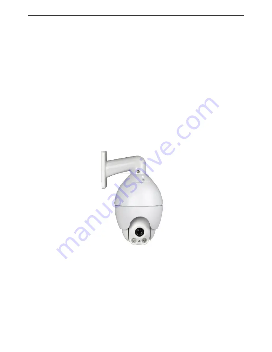
HD-AHD Intelligent High Speed Dome 

User Manual 


Thank you for purchasing our produdts . Please do not hesitate to contact us if there is any question. 

Please read this manual careful before instation or application 

(Note

This manual is subject to change without notice) 

Содержание RPTZ1080-10X

Страница 1: ...ome User Manual Thank you for purchasing our produdts Please do not hesitate to contact us if there is any question Please read this manual careful before instation or application Note This manual is subject to change without notice ...

Страница 2: ...nstallation 18 Chapter3 Installation 3 1 Packing Checking 21 3 2 Installation 22 3 3 Dip Switches Dome Address Protocol and Baud Rate 28 Chapter 4 Installation Method of Different Brackets 4 1 Dimensions 31 4 2 Wall Mount 33 4 3 Pending Mount 34 4 4 Corner Adapter 37 Chapter 5 Operation Guidance 5 1 Wiring 41 5 2 Protocol and Baud Rate Setting 42 5 3 Dome Address Setting 42 5 4 Install the Camera ...

Страница 3: ...ree Submenu 47 Appendix 1 Lightning and Surge Protection 55 Appendix 2 RS485 BUS Connection 55 Appendix 3 Common Problems and Solutions 57 Note 1 The key IRIS mentioned in this manual is equal to OPEN and IRIS is equal to CLOSE PRESET is equal to SET i e to edit preshot while PREVIEW is equal to ACK i e call preshot FOCUS is equal to FAR ...

Страница 4: ...tly followed during the installation and application of this product 2 Please use standard power adapter DC12V 2A 3 Do not connect several devices to one power adapter as adapter overload may cause over heat or fire hazard 4 Please disconnect power during wiring and disassembling Operation is not allowed when connected to power 5 When the product is installed on wall or ceiling the devices should ...

Страница 5: ...ck and do not expose it to high electromagnetism radiation Avoid the equipment installation on viberating surface or shocking places ignorance can demage the equipment 2 Do not install the dome in extremely hot onver 60 or cold below 40 or damp locations 3 Indoor domes should be kept away from rain and moisture ...

Страница 6: ...HD AHD Intelligent High Speed Dome User Manual 5 Chapter 1 Introduction 1 1 Product Introduction 1 2 Appearance 1 3 Functions 1 4 Technical Data 1 5 Short cut Commands 1 6 Glossary ...

Страница 7: ...t in zoom lens and the decoder controller are used together It s driven by precise stepper motor and thus responsive stable and trembling free at any speed The excellent performance and complete functions has made it a high tech security product 1 2 Appearance Top Housing Camera Module Side cover Connector Bracket Camera frontal cover ...

Страница 8: ...D AHD Intelligent High Speed Dome User Manual 7 Top extemal Housing Infrared light Side cover Connector Bracket Down extamal Housing Camera Module Light sensor RPTZ1080 10X 427 Dome RPTZ1080 10X 428 Dome ...

Страница 9: ...restore in the menu User can set how the camera rotates after start l Color B W can be set to be Color B W or Auto l 6 PTZ Pattern can record all P T Z tour l Automatic changing of P T speed the P T speed reduces proportionally according to zoom times l 128 presets accuracy less than 0 1º the dome targets a specific location can be set and changed l Flexible and resettable auto scan speed 1 9 degr...

Страница 10: ...Zoom 10 X f 5mm 50mm White Balance Auto D N ICR IR light Source Varical focal IR Ⅲ generation IR Wave Length 850nm IR Control Auto Manual IR life more than 20 000 hours IR LED QTY 2 X 18 Infrared Distance 50 M IR Angle 30 45 Proccessor 32 bit ARM Address 0 255 Compatible with hard address and soft address Pan Range 360 Endless Pan Speed 0 1 S 240 S 1 64 degree optional Tilt Range 0 90 Tilt Speed 0...

Страница 11: ...nication RS485 BUS Coaxitron control Baud Rate 2400 4800 9600 19200bps Optional Input Power DC12V 2A Consumption 15W Video Out AHD BNC Video Transmitting Distance 400 m Weight 1 2Kg Installation L type bracket and Ceiling Mount forRPTZ1080 10X 427 Wall mount bracket and Pendent bracket for RPTZ1080 10X 428 Certificates ROHS CE FCC ...

Страница 12: ...ome Position PREVIEW 69 OSD ON OFF PRESET Screen ON OFF PREVIEW 70 Digital Zoom ON NA PRESET Digital Zoom OFF NA PREVIEW 71 Auto Focus PRESET Manual Focus PREVIEW 72 Auto Iris NA PRESET Manual Iris NA PREVIEW 73 White Balance Auto PRESET White Balance Manual NA PREVIEW 74 Indoor Mode NA PRESET Outdoor Mode NA PREVIEW 75 ATW NA PRESET one push WB NA PREVIEW 76 Image Freeze ON NA PRESET Image Freeze...

Страница 13: ...sition in 8 Minute PREVIEW 83 Home Position in 10 Minute PRESET Home Position OFF PREVIEW 84 Run 1st 2 Point Scan PRESET PREVIEW 85 Run 2nd 2 Point Scan Default is 1st one PRESET Set 2nd 2 Point Scan Reserved PREVIEW 86 Run 3rd 2 Point Scan Reserved PRESET Set 3rd 2 Point Scan Reserved PREVIEW 87 2 point scan at low speed When speed is 64 degree this command is to record the speed PRESET Set start...

Страница 14: ...rator logo in Reserved PRESET User log in Reserved PREVIEW 92 Run Pan Scan PRESET Dome information dispaly Will disappear in 3 S or when joystick moved PREVIEW 93 Run 16 preshots PRESET Restart Press PRESET 93 three times continually PREVIEW 94 PRESET PREVIEW 95 Open OSD Menu PRESET PREVIEW 96 PRESET PREVIEW 97 Run 1nd Pattern PRESET PREVIEW 98 Run 2rd Pattern PRESET PREVIEW 99 PRESET PREVIEW 100 ...

Страница 15: ...ved PREVIEW 110 Return to factory setting Press PREVIEW 110 once then press PRESET 110 twice and press PREVIEW 110 once PRESET 1 6 Glossary Soft Address User can set soft address in this dome thus make it easier in installation and application General Address Address 0 is the general address which menas the controlling devices can control any dome in a system by this address no matter what the cur...

Страница 16: ...es flips the camera starts moving upward as long as you continue to hold the joystick in the down position This function can be realized by image center flip depending on different camera models The feature can be enabled disabled through the menu PRESET PRESHOT Each of the user definable presets can be programmed to use pan tilt camera settings and other settings When preset is called the dome wi...

Страница 17: ... the camera to focus automatically to maintain clear video images User can also press FAR and NEAR to focus It will resume auto focus when user do P T Z controlling Auto Iris The auto iris enables the camera to iris automatically to maintain clear video images User can also press OPEN and CLOSE to focus It will resume auto iris when user do P T Z controlling Backlight Compensation When there is br...

Страница 18: ...HD AHD Intelligent High Speed Dome User Manual 17 Chapter 2 Precautions to installation 2 1 Preparation 2 2 Precautions to installation ...

Страница 19: ...g to required transmitting distance Basic requirements of coaxial cable 1 75Ω 2 Brass cable 3 95 copper braid tinned 2 2 Precautions to installation 1 Read the this manual carefully before installation 2 The power supply and the voltage should be the same as indicated on the cable Standard voltage is DC12V the voltage should be within DC12V 10 Long time working of dome under too low or too high vo...

Страница 20: ...HD AHD Intelligent High Speed Dome User Manual 19 Right Wiring Wrong Wiring ...

Страница 21: ...HD AHD Intelligent High Speed Dome User Manual 20 Chapter 3 Installation 3 1 Package Checking 3 2 Installation 3 3 Dip Switches Dome Address Protocol and Baud Rate ...

Страница 22: ...acket 3 Power Sypply 4 User Manual 5 Quality Certificate 6 Warranty Card Power Supply Optional User Manual 3 1 2 Packing list of outdoor 1 Integrated Camera 2 Bracket Integrated Camera Bracket Optional 3 Power Sypply 4 BNC Cable 5 Screw Pack 6 User Manual 7 Quality Certificate Power Supply Optional BNC Cable 8 Warranty Card Screw Pack User Manual Note non original packing material may cause damage...

Страница 23: ...Indoor Dome 3 2 1 1 Fix L bracket on the wall 3 2 1 2 Take down the ceiling plate from dome assemble it into L Bracket then install dome into celling plate put it into slot rotate from the right side then fasten the ceiling plate by PM2 5 8 screws from side of speed dome as shown in picture ...

Страница 24: ...wered up 3 2 3 2 Multi dome device connection When connecting many dome devices together the user can embed multi device system with auxiliaries such as arrester device video matrix DVR and alarm box for system integration DC12V Power supply of dome device which will convert 110V 60HZ to 220V 50HZ input to DC12V output and supply to the dome device RS 485 Bus It is for the control signal RS 485 si...

Страница 25: ...e following picture Please refer to Chapter 4 for installation of different brackets 3 2 2 2 For wall mount bracket get out the upper housing from from the carton and install it with the bracket Please wrap the connecting part between the upper housing and the bracket with teflo tapes see following picture to make it water proof if it s an outddor camera ...

Страница 26: ...n The one dome device connection allows the user learn the wiring quickly and also makes the installation adjusting testing and exhibition easier Read the below chart carefully for connection when you use the apparatus for the first time Any worng wiring may cause permanent damage or damage to other equipments AHD DVR AHD VIDEO ...

Страница 27: ...devices together the user can embed multi device system with auxiliaries such as arrester device video matrix DVR and alarm box for system integration DC12V Power supply of dome device which will convert 110V 60HZ or 220V 50HZ input to DC12V output and supply to the dome device RS 485 Bus It is for the control signal RS 485 signal output of controller connecting to the communication input terminal...

Страница 28: ...wn remove the cover of Dip switches board near camera set dome address and baud rate There are two dip switch SW1 SW2 on master board which used for setting dome address baud rate and Protocol see 3 3 dip switches setting SW2 Dome address setting SW1 Protocol and baud rate setting ...

Страница 29: ... rate otherwise the dome cann t be controllered The dome camera should be restarted if there is in the dip switches 3 3 2 Dome address as shown in SW2 Dip Switch Protocol 1st Dip 2nd Dip Auto OFF OFF DYNACOLOR ON OFF Dip Switch Baud rate 3rd Dip 4th Dip 2400 OFF OFF 4800 ON OFF 9600 OFF ON 19200 ON ON Dome Address Dip Switch This is Dome address of Dome 1 Protocol Baud Rate Dip Switch D PELCO P et...

Страница 30: ...o protocol 2400bps baud rate and 1 dome address Setting to add together the corresponding numbers of those DIP at ON and you get the dome address Dome Address counting example 1 2 4 8 16 32 64 128 2 4 16 2 4 16 22 Dome address is 22 Dip switch corresponding numbers Corresponding numbers Corresponding numbers ...

Страница 31: ...HD AHD Intelligent High Speed Dome User Manual 30 Chapter 4 Installation of Different Brackets 4 1 Dimensions 4 2 Wall Mount 4 3 Pending Mount 4 4 Corner Adapter ...

Страница 32: ...HD AHD Intelligent High Speed Dome User Manual 31 4 1 Dimensions 4 1 1 Wall Mount Bracket 4 1 2 Pendant Bracket 4 1 3 Corner Adapter ...

Страница 33: ...HD AHD Intelligent High Speed Dome User Manual 32 4 1 4 Wall Mount Adapter 4 1 5 Pole Mount Adapter ...

Страница 34: ...ght of dome and all the accessories Procedure 1 Make a Hole and Fix the Anchor Bolts Drill 4 holes on the wall according the dimension of wall mount bracket and insert the M8 anchor bolts Prepared by the user into the holes Procedure 2 Run the BNC cable through the wall mount bracket Procedure 3 Fix the Wall Mount Bracket on the Wall Fix the 4 M8 screw caps with plain washers and then screw them w...

Страница 35: ...HD AHD Intelligent High Speed Dome User Manual 34 4 3 Pending Mount Installaiton 4 3 1Accessories 1 Pending Pan Used for pending mount installation should be used together with pipe and connector ...

Страница 36: ...n endure at least 5 times of the weight of dome and all the accessories Procedure 1 Install the Ceiling Pan Make 4 holes on the ceiling accordingly with the holes on the ceiling pan insert the anchor botls then run the BNC cable throughthe ceiling pan Then aim the 3 holes on the ceiling pan to the inserted anchor bolts and fix with M5 screw Note The length of BNC cable outside ceiling pan should b...

Страница 37: ...the BNC cable through the pipe and connector Thenfix the pipe with the ceiling pan by M4 Screw Picture Procedure 3 Dome Installation Insert BNC cable to connector on top of the dome housing and then connect the top of domehousing with pendant bracket connector and fix by M4 screw Then install the dome according to Chapter 3 ...

Страница 38: ...Installation 4 4 1Accessories 1 Wall Mount Bracket Applcable for indoor and outddor dome 2 Corner Adapter Should be used together with wall mount bracket 3 Accessories Screws Hexagon Bolts M8 Spring Washers and Plain Washers Prepared by user 4 4 2 Installation Procedures ...

Страница 39: ...ts Run the BNC cable through the center hole then fix the corner adapter to the znchor bolts by screw caps and washers Precaution The Anchor Bolts are prepared by the user Assure the cable is long enough If the dome is used outdoor put glass glue to make it water proof Procedure 2 Install wall mount bracket to corner bracket Use the provided Bolts Spring Washers and Plain Washers to mount the Wall...

Страница 40: ...ome User Manual 39 Procedure 3 Install the speed dome Insert the BNC cable through the wall mount bracket then screw the bracket with the dome and fasten with anchor bolts M4 then install the speed dome according to Chapter 3 Picture ...

Страница 41: ...eed Dome User Manual 40 Chater 5 Operation Guidance 5 1 Wiring 5 2 Protocol and Baud Rate Setting 5 3 Dome Address Setting 5 4 Install the Camera Module 5 5 Connect to Power 5 6 Controller Setting 5 7 Testing 5 8 Finish Testing ...

Страница 42: ...HD AHD Intelligent High Speed Dome User Manual 41 5 1 Wiring Do not connect to power 5 1 1 Wiring for indoor dome 5 1 2 Wiring forRPTZ1080 10X 428 dome ...

Страница 43: ...ome is connected to power dome should be restarted if there is any change in the setting In left picture Dome address is 1 Please refer to 3 3 2 The Dip Swich is on PCB Board inside the dome 5 4 Install the Camera Module Please refer to Camera Module Installation 1 Connect camera module to FPC cable Dome Address Setting and Baud Rate Setting Do not set when dome is connected to power dome should b...

Страница 44: ...Dome User Manual 43 CTU10AH108 2 Connectors for convert board and master board Ear board 6PIN cable inserting 4PIN 8PIN cable inserting Camera FPC 3 Connectors for convert board and camera holes FPC connector 4 Installation finished ...

Страница 45: ... self checking of both dome rotating and camera module you can see imageonmonitor 5 6 Controller Setting For the controller the protocol baud rate and address should be the same as the dome pleaserefer to the user manual of cotronller for the detailed setting Precaution If the protocol of dome is Auto then protocol of controller can be PELCO D PELCO P ULTRACK VICON etc but baud rate and address sh...

Страница 46: ...te joystick to zoom in and zoom out or to press the key TELE Zoom In and WIDE Zoom Out on the controller This means the communication of dome and camera module is good For operations please refer to the next Chapter for details 5 8 Finish Testing Summary 1 If everything normal in 5 7 it means the system works well Please don t change the wiring or any setting to avoid failure in system 2 If there ...

Страница 47: ...HD AHD Intelligent High Speed Dome User Manual 46 Chapter 6 Operation in OSD Menu 6 1 The English OSD Menu 6 1 1 Main Menu 6 1 2 Menu Tree Submenu ...

Страница 48: ...k left and right to enter the chosen item andor to change setting 3 Press IRIS to exit or return to previous item menu 6 1 2 Menu Tree Submenu All the submenus are clearly shown in this menu tree Note the following icons means there is drop down menu down up RPTZ1080 10X 1 Language English 2 Display Setting 3 Control Setting 4 System Setting 5 Camera Setting 6 Function Setting 7 Exit Language Opti...

Страница 49: ...INPUT SOFT ID 1 0 255 0 Move joystick left right to choose 3 INPUT S N 4 S N 0989694 5 SOFT BAUD OFF 2400 4800 9600 19200 Move joystick left right to choose 6 RETUTN Move joystick left right to Exit 2 PAN AND TILT SETUP Set Pan And Tilt Move joystick left right to enter 1 PAN REVERSE OFF ON Move joystick left right to choose 2 TILT REVERSE OFF ON Move joystick left right to choose 3 5 TILT LIMIT O...

Страница 50: ...LEAR MEMORY Clear Memory Move joystick left right to enter 3 RESTORE DEFAULT Restore Def Setting Move joystick left right to enter 4 CAMERA RESET N A 5 RETURN Move joystick left right to Exit 5 CAMERA SETTING Move joystick left right to enter 1 SHARPNESS 9 Move joystick left right to choose NOTE SHARPNESS 0 15 2 CAMERA EXPOSURE Move joystick left right to enter 1 MODE AUTO Move Joystick left right...

Страница 51: ...e NOTE NR LEVEL 0 5 7 WDR OFF ON Move Joystick left right to choose 8 D N MODE COLOR Move Joystick left right to choose NOTE D N MODE COLOR B W AUTO 9 RETURN Move joystick left right to exit 6 FUNCTION SETTING Function Setting Move joystick left right to enter 1 PRESET Preset Setup Move joystick left right to enter 1 NUMBER 1 64 Move Joystick left right to choose 2 SET PRESET Move joystick left ri...

Страница 52: ...choose the position 6 NAME DISPLAY OFF ON Move joystick left right to choose 7 RETURN Move joystick left right to Exit 3 VECTORSCAN Move joystick left right to exit 1 NUMBER 1 7 Move joystick left right to choose 2 PROGRAM VECTORSCAN Move joystick left right to enter 1 SEQUENCE 1 16 Move joystick left right to enter 2 ELEMENT 0 Move joystick left right to choose NOTE ELEMENT PRESET VECTORSCAN TOUR...

Страница 53: ...right to choose NOTE NUMBER P 1 64 V 1 7 T 1 6 3 DELAY 60 Move joystick left right to choose NOTE DELAY 1 255 4 OPERATION ON OFF Move joystick left right to choose 5 RETURN Move joystick left right to Exit 5 PAN SCAN SETUP Move joystick left right to enter 1 START POINTER Move joystick left right to enter 2 END POINTER Move joystick left right to enter 3 SCAN SPEED 3 Move joystick left right to ch...

Страница 54: ... enter 5 RETIRN Move joystick left right Exit 7 IRLED CONTROL Move joystick left right to enter 1 IRLED MODE AUTO OFF ON Move joystick left right to choose 2 THRESHOLD 10 Time Delay Seconds Move joystick left right to enter NOTE 3 60S 3 SENSITVITY 5 Move joystick left right to choose NOTE SENSITVITY 1 8 4 RETURN Move joystick left right to Exit 8 RETURN Move joystick left right to Exit 7 EXIT Move...

Страница 55: ...HD AHD Intelligent High Speed Dome User Manual 54 Appendix 1 Lightning and surge protection Appendix 2 RS485 Bus Connection Appendix 3 FAQs and solutions ...

Страница 56: ...n for installation and wiring with lightning protection and grounding in mind should be combined with the lightning protection consideration of the building and conform to the related national standards and industry standards 6 The system should be equipotentially grounded and the grounding equipment must satisfy double request of system anti jamming and electric safety and it must not appear shor...

Страница 57: ...through the DIP switch on the communications board 4 Problems in the Practical Application Normally users adopt star shape connection method in construction under this situation the terminal resistors must be connected between two farthest devices But this connection method is not satisfy the requirement of the RS485 industry standard so that it will lead to some problems such as signal reflection...

Страница 58: ...VIEW to display OSD menu After self check OSD menu can only display when there is image Problem with main control board Change main control board 4 Text or image distorted flopping or garbled Signal was interferced or the camera was targeting at electronic image Connect dome to ground or turn off surrounding electronic equipment electrical high frequent equipment signal generator rotate the camera...

Страница 59: ...readjust mechanical installation 9 Normal seld cheking can be controlled Wrong setting Reset protocol baud rate address RS485 not connect well Check connection 10 Dome not respond good to keyboard Communicate distance too long Add driver Usually it s the problem with the coonection RS485 not connect well Check wring Slipping damaged Change slipping RS 485 protecting pipe damaged RS 485 protecting ...

Отзывы: