


Series 1780 Dynamometer User Manual V1.1
Document ID: Q2D4F5
Publish date: 2020-03-06
To avoid mistakes using wrong screws in the Series 1780 assembly, please keep the fasteners
in the bags until you need to use them. We did not prepare any spare fasteners in the bags
except for the motor mounting. Keep all the empty fastener bags in case that you need to
disassemble the structure, and place the fasteners back in those bags with labels.
4.1.2 Assembly the upper part of the support
Please follow these instructions to assemble the support:
❏
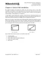
Unpack the stand structure box 1 (#TJLD), and get two T-slotted single beams 7” long
(#NWGF) and two T-slotted single beams 4’ long (#HJXQ).
❏
Place all these four T-slotted frames (#NWGF and #HJXQ) on a work table.
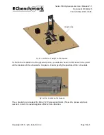
Fig. 4.4: T-slotted frame 4’ long (#HJXQ)
❏
Open the beam fasteners bag (#WVKM) from the accessories and fasteners for
assembly box (#BCJE). Take eight end-feed button head screws 5/16-18 - 11/16” long
(#KEDB) and eight end-feed T-nuts 5/16-18” (#YREC) out of the bag.
❏
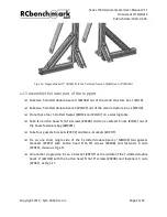
Take four gussets brackets (#YKPV) out of the box.
❏
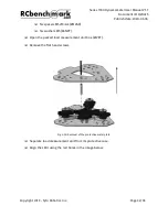
Use the button head screws (#KEDB) and T-nut (#YREC) to connect one gusset bracket
(#YKPV) with the 4’ beam (T-nut inside the slot of the T-slotted beam). Do not fully
tighten the fasteners. You may slide the gusset, the screw and T-nut while untighten,
as image shown:
Copyright 2019 - Tyto Robotics Inc.
Page 19/65


