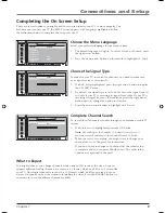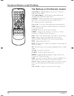
Connections and Setup
10
Chapter 1
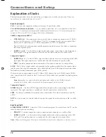
Explanation of Jacks
This section describes the jacks and cables you might use to make connections. There are
several ways to connect devices to your TV.
Back Panel (right)
VGA
Connect your computer to this jack using a 15 pin D-sub cable.
VGA AUDIO (Stereo mini jack)
Use to obtain sound when a PC is connected to the VGA
jack. Use a 3.5 mm stereo mini pin cable (sometimes referred to as 1/8” stereo mini pin) to
connect a PC to your TV. Go to page 8 for more information.
CMPT (Component) INPUT
• Y
Pb/Cb
Pr/Cr
For connection of devices that have component output jacks (Y Pb Pr),
such as an HD receiver, or DVD player. The TV’s Component jacks can recognize if the
device you’re connecting to is Y Pb Pr compatible or Y Cb Cr compatible.
The Y Pb/Cb Pr/Cr jacks provide excellent picture quality because the video is separated
into three separate parts.
•
AUDIO L
and
R
Use the left and right audio jacks when connecting to the Component
video inputs. The right connector is usually red; the left connector is usually white.
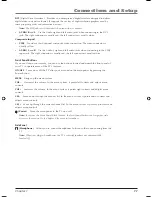
Composite Input 1
• AUDIO
R
and
L
Use the AUDIO1 right and left audio jacks when connecting to the VID1
input jack. The right connector is usually red; the left connector is usually white.
• VID1
Provides composite video connection. The video connector is usually yellow.
S-VID
The S-Video (super video) jack provides better picture quality than the regular video
jack because the color (chrominance, also called chroma) part of the signal is separated from
the black and white (luminance) part of the picture.
If a device you’re connecting to your TV (like a DVD player) has an S-VIDEO and a VIDEO
jack, connect the DVD player to the TV with an S-Video cable (not provided) for better picture
quality.
Note:
Remember to connect the left and right audio cables to the AUDIO1 In jacks
because the S-Video cable carries only the picture signal, not the sound.
Composite Input 2
AUDIO R
and
L
Use the AUDIO2 right and left audio jacks when connecting to the VID2
input jack. The right connector is usually red; the left connector is usually white.
VID2
Provides an additional composite video connection. The video connector is usually
yellow.
ANT
Lets you connect a coaxial cable to receive the signal from the antenna, cable, or cable
box.
Back Panel (left)
AUDIO/VIDEO OUTPUT
Connect a VCR to record programs. You must leave the TV on the
same channel you are recording.
•
VID OUT
Provides composite video connection and connector is usually yellow.
•
AUDIO L
and
R
Use the Audio left and right audio jacks when connecting to the VID
OUT jack. The right connector is usually red; the left connector is usually white.
Note:
When recording from this output, remember to tune to the channel you want to record.
1652880A.indb 10
1652880A.indb 10
8/22/05 4:15:50 PM
8/22/05 4:15:50 PM
Содержание L26W11
Страница 4: ...This page intentionally left blank ...
Страница 35: ...This page intentionally left blank ...


