UM-1096
Revision A
12
4.3
Normal Operation
During normal operation the sensor data is displayed on one of three data display screens as shown
below. To cycle through the data display screens, use a magnet and swipe the
Next
key until the desired
screen is reached.
Figure 8 SensePoint Data Display Screens
4.4
Fault Condition
The Fault alarm is used to indicate a condition when there is a failure from the sensor or an out of range
state has been reached. It is recommended to set the fault alarm level to -10% of the span value. For
example, if an H2S sensor is installed with a span value of 100, the fault should be set at -10, or if an
oxygen sensor is installed with a span value of 25, the fault setting should be -2.5.
If relays are installed, the Fault relay is always Failsafe. This is necessary for the relay to de-energize in
the event there is a loss of power, so that a Fault will be indicated.
If relays are not installed, a Fault condition will only be indicated by the display color changing to red
and/or the red Fault LED flashing.
Figure 9 SensePoint Fault Screen
Содержание 10-0517
Страница 4: ...UM 1096 Revision A III Drawings 44...
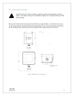
Страница 10: ...UM 1096 Revision A 5 Figure 2 Remote Sensor Enclosure Mounting Dimensions...
Страница 26: ......
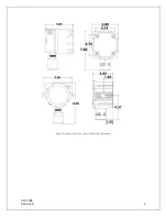
Страница 49: ...UM 1096 Revision A 44 Appendix 9 Drawings Drawings Figure 13 Mounting Dimensions...
Страница 50: ...UM 1096 Revision A 45 Figure 14 10 0517 CPU Board Figure 15 10 0533 I O Board...
Страница 51: ...UM 1096 Revision A 46 Figure 16 10 0532 Modbus Relay Board...

