background image

RBR#0008818revA

 –  

17


1.

2.

3.

4.
5.

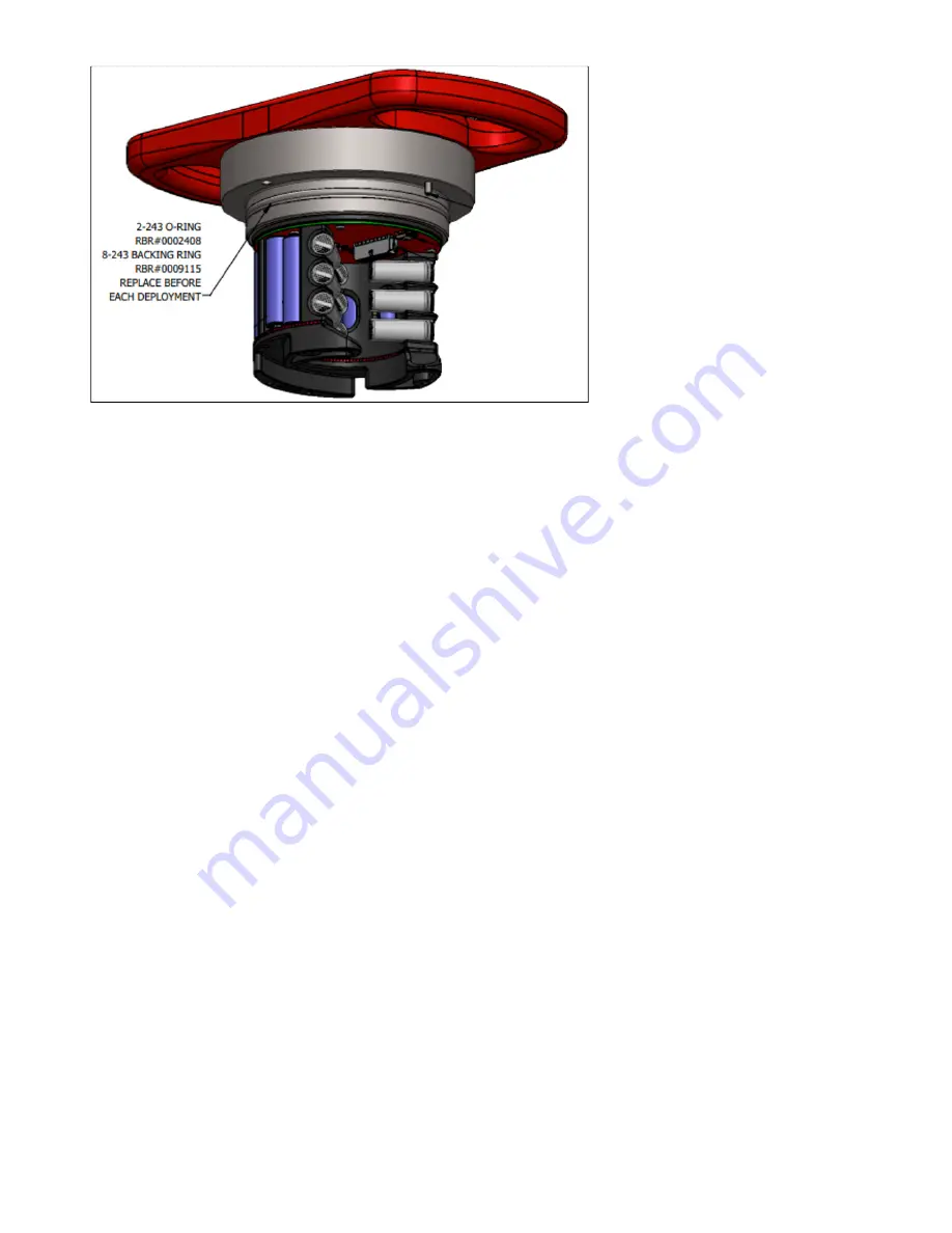
Inspecting O-rings

Pay attention to the following areas:

The surface of the O-ring itself
The mating surface on the inside of the case between the threads and the open end
The inner surfaces of the groove in the end cap where the O-ring sits

Any dirt present should be removed by wiping thoroughly with a soft, lint-free cloth. When cleaning, never use any 
material or tool which could scratch the O-ring or any of its mating surfaces. If any dirt is present in the O-ring groove, 
then the O-ring should be removed as described below to allow thorough cleaning of the groove. If an O-ring needs to 
be removed for any reason, it should be replaced.

If the O-ring is scratched, cut, distorted, perished or defective in any other way it must be replaced. If any of the surfaces 
of the O-ring groove are scratched, pitted or otherwise damaged, the logger may need to be returned to RBR for 
refurbishment: please contact us for advice.

Replacing an O-ring

Lever the O-ring from its groove. Use a soft plastic or wood tool; do not use a metal screwdriver or any 
other tool which may scratch the surfaces of the O-ring groove, doing so will probably render the end 
cap useless. Slide the O-ring out of its groove and off the logger. The O-ring may need to stretch quite 
a bit as it is pushed off; this requires some effort but can be done by hand.

Thoroughly clean the O-ring groove, taking great care not to scratch or damage it in any way. Inspect it 
carefully, and contact us for advice if it appears damaged. Apply a light film of silicone grease to all 
three inside surfaces of the groove, being careful not to trap any dirt, hairs or lint.

Select the proper O-ring, see part numbers below, and make sure it is not damaged. Lubricate it with a 

very light film of silicone grease to ease its installation.
Install the new O-ring by pushing it into place and popping it into its groove.
When the new O-ring is in place, inspect it once more for scratches and dirt, and wipe away any 
silicone grease deposited on the end cap.

Содержание quartz3 Q

Страница 1: ...rbr global com INSTRUMENT GUIDE Q...

Страница 2: ...Installing desiccant 13 6 4 Twist activation 13 6 5 Wi Fi feature 14 6 6 Maintenance and repairs 15 6 6 1 Instrument calibration 15 6 6 2 O rings 15 Inspecting O rings 15 Replacing an O ring 16 6 6 3...

Страница 3: ...wer draw 24 6 7 2 Paused 24 6 7 3 USB Power 24 7 Appendix 25 7 1 Appendix A Product drawing 25 7 2 Appendix B Paros interface drawing 27 7 3 Appendix C Anti biofouling mesh assembly 28 7 4 Appendix D...

Страница 4: ...nt and will provide the information to deploy and maintain it It is written specifically for the RBRquartz3 QYou can access the RBR instrument guide on the USB data stick provided when you purchase a...

Страница 5: ...RBR 0008818revA 5 3 Revision history Revision No Release Date Notes A 04 May 2020 Original...

Страница 6: ...by us The liability of RBR Ltd extends only to the replacement cost of the instrument The customer will bear all costs of shipment to us for repair all other costs including return shipment will be b...

Страница 7: ...rement schedules and burst sampling permit applications for tide wave and sea level measurements The RBRquartz Q has a large memory capacity and USB C or optional Wi Fi download for large data files T...

Страница 8: ...R 0008818revA 8 5 1 2 Included in Shipment Item No Description 1 RBRquartz3 Q 2 8xAA batteries 3 RBR quick start guide 4 O ring removal tool 5 Replacement O rings 6 Spare desiccant 7 Silicone grease 3...

Страница 9: ...wn Battery end cap defined in the order and may not be as shown 5 2 Specifications Physical Weight in air 2300g Size 510mm x 100mm Displaced Volume 2395cm3 Housing Plastic Depth rating 750m Operationa...

Страница 10: ...iumirondisulfide_psds pdf can also support NiMH Alkaline and Lithium ion Marine temperature standard Range 5 to 35 C Accuracy 0 002 C Time constant 30s embedded Typical stability 0 002 C year Depth Ra...

Страница 11: ...y until the O ring is clear of its mating surface in the body This ensures that it will not eject at high speed should the interior of the logger become pressurized Closing the logger is exactly the r...

Страница 12: ...ap from the logger see Opening and closing the logger 2 Using both thumbs press down on the symbols on the battery cover and slide in the direction of the arrow The battery cover can then be folded up...

Страница 13: ...is securely placed 3 Replace battery end cap 6 4 Twist activation All loggers are shipped with this feature enabled This allows the instrument to be enabled without a schedule To activate or deactivat...

Страница 14: ...has been enabled or not allowing for connection to Ruskin downloading data and programming the deployment See image below for an example use case If you have enabled the Wi Fi feature on your logger a...

Страница 15: ...y logger s seal depends upon its O rings not the end cap tightness Therefore proper O ring maintenance is crucial Inspecting O rings Pay attention to the following areas The surface of the O ring itse...

Страница 16: ...t is not damaged Lubricate it with a very light film of silicone grease to ease its installation Install the new O ring by pushing it into place and popping it into its groove When the new O ring is i...

Страница 17: ...bishment please contact us for advice Replacing an O ring Lever the O ring from its groove Use a soft plastic or wood tool do not use a metal screwdriver or any other tool which may scratch the surfac...

Страница 18: ...lled with a buffer which is connected to the environment via a tube The mounting of the Paroscientific Digiquartz sensor and the connection to the sensor end cap are described in Appendix B Paros inte...

Страница 19: ...y remove the set screw 0004579 The full anti biofouling assembly drawing is available in Appendix C Anti biofouling mesh assembly Filling purging debris from the buffer tube While holding the instrume...

Страница 20: ...semble as per Figure 1 and instructions below Install the set screw with the 0 7mm hole 0004579 using the 3mm hex key When installing the set screw the oil will be displaced and spill into the mating...

Страница 21: ...e Part Number Description 0008765 Anti biofouling Mesh hardware kit for BPR Includes the items below 0004583 14mm Dia Nickel Copper Anti biofouling Mesh 0004592 Upper Mesh Insulator Disk 0004591 Lower...

Страница 22: ...tion Remove anti biofouling mesh Follow the instructions for accessing the buffer tube as described in Corrective maintenance Installation of the calibration adapter Apply a thin layer of grease to th...

Страница 23: ...us for an RMA number and please use the following shipping address RBR Ltd 95 Hines Road Unit 5 Kanata Ontario CANADA K2K 2M5 Telephone 1 613 599 8900 For those who are shipping from outside of Canada...

Страница 24: ...y draw power from this source and not consume the internal batteries For a logger that is powered by an external source the internal batteries serve as backup power in the event the external source fa...

Страница 25: ...RBR 0008818revA 25 7 Appendix 7 1 Appendix A Product drawing...

Страница 26: ...RBR 0008818revA 26...

Страница 27: ...RBR 0008818revA 27 7 2 Appendix B Paros interface drawing...

Страница 28: ...RBR 0008818revA 28 7 3 Appendix C Anti biofouling mesh assembly...

Страница 29: ...RBR 0008818revA 29 7 4 Appendix D Calibration adapter installation...

Отзывы: