RBH Access Technologies Axiom III PC-100 Скачать руководство пользователя страница 20


24 February, 2010 

RBH Access Technologies Inc. 

20 of


26


TB61_PC-

100 for AxiomV™  

NC100 Firmware Version 

Version 760 (or  higher) is required for use of wavetrend readers.  Selecting the 
72-bit  WTND  format  for  an  access  point  will  enable  the  use  of  the  long-range 
readers and credentials. 

The NC100 firmware has been designed to ignore the continuous stream of card 
data  from  the  wavetrend  readers  unless  the  card  has  moved  from  one  zone  to 
another.  A special buffer has been reserved 

to store ID‟s along with a timer and 

RSSI  value.    The  timer  is  refreshed  on  every  transaction  for  each  card  in  the 
buffer.  If the timer times out the card will be reported as missing.  The extended 
unlock time is used as the value for this timer.  A value of 60 seconds works well 
with 10 credentials. 
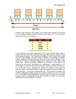
RSSI Values 

The  RSSI  value  is  the  Received  Signal  Strength  Indicator.    This  value  ranges 
from 50 to 255 depending upon how close the card is to the reader and how the 
reader is set up. 

If a reader has an antenna attached, the RSSI value of a card 3 meters away will 
be around 100.  Without an antenna the same card will report around 60. 

The  RSSI  value  is  displayed  in  the  AXIOM  cards  monitor  screen.    This  can  be 
used  to  adjust  the  RSSI  threshold  so  that  the  zone  area  can  be  limited  to  a 
particular distance. 

RSSI Threshold 

The  DHO  warning  time  is  used  as  the  RSSI  threshold  value.    To  use  a  value 
greater  than  127  select  minutes  and  calculate  adding  128  to  the  value.    As  an 
example:  to  achieve  an  RSSI  value  of  140,  set  the  time  to  minutes  and  use  a 
value of (140 

– 128) 12.  The received RSSI value will be displayed in the AXIOM 

V cards monitor. 

RSSI Background Messages 

A  credential  will  transmit  its  ID  every  1.5  seconds.    This  message  is  translated 
into  an  RC-2  style  72-bit  wiegand  style  message  by  the  PC100.    Part  of  the 
message contains the RSSI value of the card.  Whenever the value of the RSSI 
for a particular card has changed by more than the 

Unlock Time

 the message will 

be  transmitted.    To  prevent  moving  targets  from  swamping  the  C-NET  with 
unnecessary background messages the unlock time should be set to above 60.  
For stationary credentials and during installation this value may be lowered. 

Card Missing Timer 

The 

Extended Unlock Time


(EUT) is used as the “card missing” timer.  If the EUT 

is  set  to  0  a  default  value  of  60  seconds  will  be  used.    Once  a  card  has  been 
received and placed into the buffer, the timer will be decremented every second.  
When the timer times out an “Access Denied  – Missing Card” log message will 
be recorded. 

Содержание Axiom III PC-100

Страница 1: ...col 6 Point Number 7 Firmware Upgrade 7 Paradox Alarm Panel Interface 8 For a Simple Set up 8 For more complex Installations 9 IOC Setup 9 Input Groups 10 Axiom Links 10 Dipswitch Setting 10 Connections 11 Axiom Installation Procedure 11 Keypad Setup 11 Keypad Links 11 Paradox EVO Alarm Panel Setup 12 Serial Port Setup 12 Utility Keys 12 Virtual Input Usage 13 Virtual Input Programming 13 Add the ...

Страница 2: ...ET Connections 21 Wiring Readers 21 RJ45 Socket Left Side 23 Initialization of the Network 24 Wavetrend Health Monitor 24 Specifications for the L RX201 25 Appendix A 26 PC 100 Firmware 26 PC 100 Controller Firmware Version AX4401 reports version 28 26 PC 100 Controller Firmware Version AXPAR3 reports version 30 26 PC 100 Controller Firmware Version IT100V4 reports version 31 26 PC 100 Controller ...

Страница 3: ...mmunications interface can be used for a number of different applications PC 100s can be used to interface alarm panels with the AxiomV system Paradox panels and a couple of DSC panels can be interfaced this way Wavetrend long range readers are also interfaced to the AxiomV with the PC 100 ...

Страница 4: ...ll devices Into channel 1 and out from channel 2 Power 9 14vdc 150ma LEDs DIAG1 Interface status DIAG2 Axiom status Communication Channel LEDs Each communication channel has a green transmit LED and a red receive LED Normally flashing at a rate of once a second DIAG2 will flash twice as fast if the unit is offline with the Axiom Device network ...

Страница 5: ...rt on the PC100 DIP Switch Settings The Axiom Access Control System starts its IOC addresses at address 5 and can support up to sixteen devices ending at address 20 To make the DIP switches capable of selecting the range of addresses to which the emulator will respond an offset address scheme has been developed The first four switches create the start offset and the last four switches create the e...

Страница 6: ...l System When an input is armed by the Axiom System only alarm and restore messages are available Virtual Inputs have all the same software features as regular inputs This includes links operator commands and schedules the only programming that is irrelevant is circuit type Available Events State Value Armed Disarmed 0 Restore Normal 1 Alarm Abnormal 2 Alarm Trouble 3 Alarm Illegal Output Protocol...

Страница 7: ...139 155 171 187 203 219 235 251 12 12 28 44 60 76 92 108 124 140 156 172 188 204 220 236 252 13 13 29 45 61 77 93 109 125 141 157 173 189 205 221 237 253 14 14 30 46 62 78 94 110 126 142 158 174 190 206 222 238 254 15 15 31 47 63 79 95 111 127 143 159 175 191 207 223 239 255 16 16 32 48 64 80 96 112 128 144 160 176 192 208 224 240 256 Examples 1 RBH1561 C R Input 12 on panel address 14 has gone in...

Страница 8: ... eight Safesuite keypads and up to eight sequentially addressed IOC s Axiom Safesuite Address Paradox Partition Address 101 1 102 2 103 3 104 4 105 5 106 6 107 7 108 8 Whenever a partition is armed or disarmed by the Paradox system the corresponding Safesuite keypad will display the status For example if keypad number 102 reports that it is disarmed it really means that Partition 2 has been disarm...

Страница 9: ...tyle inputs use an abort delay to prevent an invalid alarm message Using an input group assigned to a virtual keypad allows the software the capability of assigning any number of inputs to each virtual keypad To truly reflect the input status of the Paradox alarm panel four links must be added to the keypad configuration Axiom Link Paradox Type Link Function Disarm Disarm Disarm all inputs except ...

Страница 10: ...arm Panel with the Axiom Access Control the Paradox inputs are mapped to virtual IOC 16 using the first eight panels on the point number table above For example Paradox panel input 88 would be mapped to IOC address 10 input 8 This input would be located in one of eight partitions in the Paradox panel programmed through the Paradox keypad Dipswitch Setting To allocate a block of IOC addresses for u...

Страница 11: ... needed in order to allow the Axiom system to arm and disarm the panel Password slot 2 is used for this purpose The password is not automatically downloaded to the virtual keypad so you must select Set User and fill in the 2 password used by the partition Keypad Links Assign the links to Disarm Home Evening and Away in the keypad configuration ...

Страница 12: ...ity Keys The Paradox Keypad has the ability to send commands to the Axiom System by pressing combinations of keys Key Combination Axiom Message 1 2 Open door 1 4 5 Open door 2 7 8 Call elevator clear 0 Toggle audio 1 on off 2 3 Toggle audio 2 on off 5 6 Toggle Video 1 on off 8 9 Toggle Video 2 on off 0 enter Clear message indicator acknowledge 1 3 Panic Alarm1 4 6 Emergency Alarm2 7 9 Fire Alarm3 ...

Страница 13: ...l input will open or close To use this feature apply a link to turn on or off the Virtual output in order to communicate an open or closed zone on the alarm panel Virtual Input Programming Follow the previous procedure for accessing the printer module programming section 4003 followed by the device serial number Sections 700 710 720 730 740 750 760 770 780 790 800 810 820 830 840 850 should be pro...

Страница 14: ...ll be no zones assigned instead the virtual IOC s will reflect the input status Using Links to arm or disarm a group of inputs allows the virtual IOC s the capability of reporting the DSC panel s inputs Using an input group assigned to a virtual keypad allows the software the capability of assigning any number of inputs to each virtual keypad To truly reflect the input status of the DSC Alarm Pane...

Страница 15: ...keypad Dipswitch Setting To allocate a block of IOC addresses for use by the DSC alarm panel you must first determine how many inputs you will need For example if you need to monitor the first 64 inputs you will need 64 16 inputs per IOC 4 IOC s The first IOC address will be 5 representing inputs 1 16 and the last IOC address will be 8 representing inputs 49 64 Use the above DIP Switch Selection t...

Страница 16: ...etermine the number of IOC s needed to reflect the number of inputs in the alarm panel Add these IOC s starting from address 5 and make them all inputs Inputs that are used for entry and exit should be given an abort delay to prevent false alarms A link may be given to the entry zone to disarm the follower zone when abnormal ...

Страница 17: ...cally downloaded to the virtual keypad so you must select Set User and fill in the 2 password used by the partition Some DSC alarm panels will allow arming without a password The password is used mostly for disarming the partition Keypad Links Assign the links to Disarm Home Evening and Away in the keypad configuration PD4401 Connect the PC4401 to the PC100 according to the drawing on page 2 The D...

Страница 18: ... the links to Disarm Home Evening and Away in the keypad configuration For example If there are 16 inputs and 2 partitions with the first partition inputs 1 8 and the second partition 9 16 there will be two input groups assigned Groups Group Name Inputs Office 1 IOC 5 inputs 1 8 Office 2 IOC 5 inputs 9 16 Links Link Name Command Arm Office 1 Reset Input Group Office 1 Arm Input Semi permanent Arm ...

Страница 19: ...ched to a network Reader RC 2 1 RC 1 Side A 2 RC 1 Side B 3 RC 2 Side A 4 RC 2 Side B 5 RC 3 Side A DIP SWITCH Settings The Axiom Access Control System starts its RC addresses at address 1 and can support up to eight devices ending at address 8 To make the DIP switches capable of selecting the range of addresses to which the emulator will respond an offset address scheme has been developed The fir...

Страница 20: ...cards monitor screen This can be used to adjust the RSSI threshold so that the zone area can be limited to a particular distance RSSI Threshold The DHO warning time is used as the RSSI threshold value To use a value greater than 127 select minutes and calculate adding 128 to the value As an example to achieve an RSSI value of 140 set the time to minutes and use a value of 140 128 12 The received R...

Страница 21: ...heck if the readers are online If a reader is not detected a Reader Tamper message will be issued If a previously offline reader is detected a Reader Tamper Restore message will be issued During the PING the diagnostic red LED will turn on D NET Connections The PC100 connects to the device network like all D NET devices supporting the redundant communications principle Connect using channel 1 and ...

Страница 22: ...n be achieved This distance is based on the RS485 standard and is dependent on the quality of the cable used RS485 termination resistors are included in each reader and therefore do not need to be added as an afterthought Data packets run bi directionally up and down this network enabling a reader to perform its functions The reader net may be supplied with power from multiple points within the ne...

Страница 23: ...24 February 2010 RBH Access Technologies Inc 23 of 26 TB61_PC 100 for AxiomV RJ45 Socket Left Side ...

Страница 24: ...y 25ms This avoids any framing errors should a reader not be able to lock onto the data stream in the correct position from start up 3 If an is received in the left RS485 port the TAG LED slave indicator is illuminated to indicate this Each reader except for the first reader on the reader network will therefore receive this character on its left hand RS485 port 4 The first reader has now been esta...

Страница 25: ...24 February 2010 RBH Access Technologies Inc 25 of 26 TB61_PC 100 for AxiomV Specifications for the L RX201 ...

Страница 26: ...e Version IT100V4 reports version 31 DSC IT100 Alarm Panel Interface firmware NC 100 firmware 8 20Beta required PC 100 Controller Firmware Version VIOC8 reports version 8 Virtual Input Output Controller with ASCII protocol NC 100 firmware 7 16 required PC 100 Controller Firmware Version WAVE55 reports version 55 Wavetrend Interface firmware NC 100 firmware 7 60 required PC 100 Controller Firmware ...

Отзывы: