A8 Overview 41
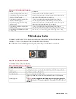
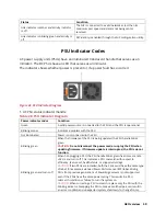
Power indicator codes
Condition
high output configuration to a low output configuration or vice versa, you
must turn off the system.
CAUTION:
AC PSUs support both 240 V and 120 V input voltages with
the exception of Titanium PSUs, which support only 240 V. When two
identical PSUs receive different input voltages, they can output
different wattages, and trigger a mismatch.
CAUTION:
If two PSUs are used, they must be of the same type and
have the same maximum output power.
CAUTION:
Combining AC and DC PSUs is not supported and triggers a
mismatch.
LCD Panel
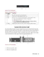
The LCD panel provides system information, status, and error messages to indicate if the
system is functioning correctly or requires attention. The LCD panel can be used to
configure or view the system's iDRAC IP address.
The LCD panel is available only on the optional LCD bezel. The optional LCD bezel is hot-
pluggable.
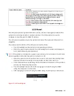
The statuses and conditions of the LCD panel are outlined here:
•
The LCD backlight is white during normal operating conditions.
•
When the system needs attention, the LCD backlight turns amber and displays an
error code followed by descriptive text.
NOTE:
If the system is connected to a power source and an error is detected, the LCD turns
amber regardless of whether the system is turned on or off.
•
When the system turns off and there are no errors, LCD enters the standby mode
after five minutes of inactivity. Press any button on the LCD to turn it on.
•
If the LCD panel stops responding, remove the bezel and reinstall it. If the problem
persists, see the Getting help section.
•
The LCD backlight remains off if LCD messaging is turned off using the iDRAC
utility, the LCD panel, or other tools.
•
LCD messaging is turned off using the iDRAC utility, the LCD panel, or other tools.
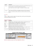
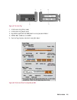
Figure 37. LCD Panel Diagram
Содержание A8
Страница 1: ...rcgs20200916 2020 2020 2020 2020 2020 2020 2020 2020 2020 ...
Страница 27: ...V12 Overview 26 Figure 21 Service Information with System Touch Points ...
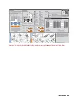
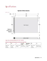
Страница 45: ...A8 Overview 44 Figure 39 System touchpoint electrical overview jumper settings and memory information ...
Страница 73: ...RAID Storage 72 Click or Choose Integrated RAID Controller 1 Figure 61 BIOS Device Settings Menu ...
Страница 75: ...RAID Storage 74 Select Virtual Disk Management Figure 63 PERC Adapter Server Profile View ...
Страница 77: ...RAID Storage 76 Under Operation choose Delete Virtual Disk Figure 65 Virtual Disk Management Select Go ...
Страница 78: ...RAID Storage 77 And Confirm that you want to Delete Figure 66 Virtual Disk Management Confirmation ...
Страница 79: ...RAID Storage 78 Once the operation has been completed click OK Figure 67 Virtual Disk Management Job Complete ...
Страница 81: ...RAID Storage 80 Select Create Virtual Disk Figure 69 Create Virtual Disk ...
Страница 82: ...RAID Storage 81 Select RAID level Figure 70 Select RAID Type ...
Страница 83: ...RAID Storage 82 Select Physical Disks Figure 71 Select Physical Disks ...
Страница 85: ...RAID Storage 84 Scroll up and Click Apply Changes Figure 73 Apply Changes ...
Страница 86: ...RAID Storage 85 Select OK Figure 74 Confirm Completion ...
Страница 88: ...RAID Storage 87 Once you have completed your settings click Create Virtual Disk Figure 76 Create Virtual Disk ...
Страница 89: ...RAID Storage 88 Confirm and Click Yes Figure 77 Confirm Operation ...
Страница 96: ...RAID Storage 95 Verify all settings and if correct click Finish Figure 84 Complete the Wizard ...

