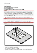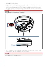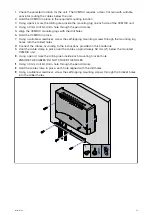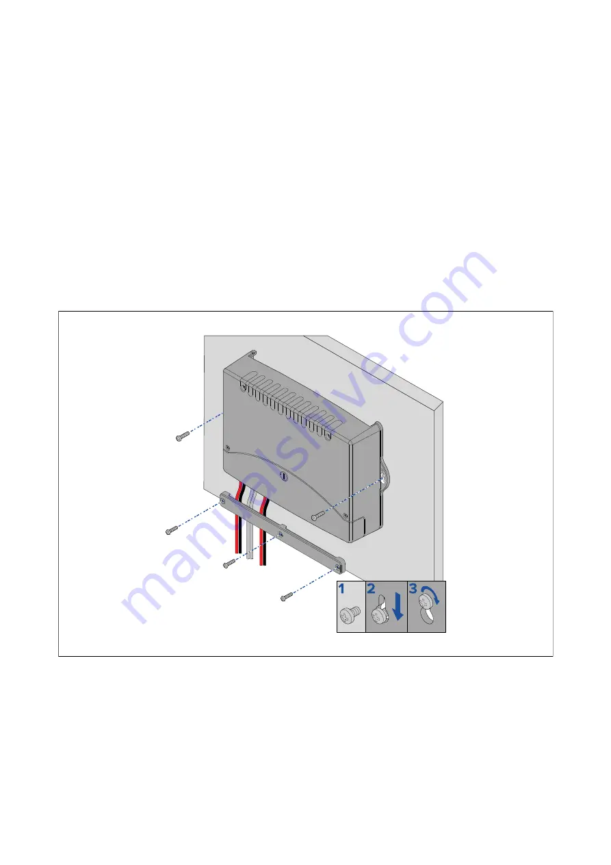
1. Check the selected location for the unit. The VCM100 requires a clear, flat area with suitable
space for routing the cables below the unit.
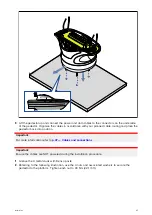
2. Hold the VCM100 in place in the required mounting location.
3. Using a pencil, mark the drilling area inside the mounting lug on each side of the VCM100 unit.
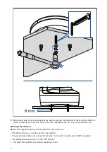
4. Using a 3 mm drill bit, drill a hole through the pencil marks.
5. Align the VCM100 mounting lugs with the drill holes.
6. Hold the VCM100 in place.
7. Using a suitable screwdriver, screw the self-tapping mounting screws through the mounting lug
holes, into the drilled holes.
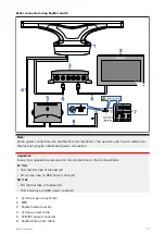
8. Connect the cables, according to the instructions provided in this handbook.
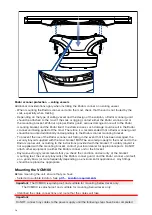
9. Hold the cable clamp in place over the cables, approximately 50 mm (2”) below the mounted
VCM100 unit.
10. Using a pencil, mark the drilling area inside each mounting bracket hole.
ENSURE THE CABLES DO NOT COVER THE HOLES.
11. Using a 3 mm drill bit, drill a hole through the pencil marks.
12. Hold the cable clamp in place, each hole aligned with the drill holes.
13. Using a suitable screwdriver, screw the self-tapping mounting screws through the bracket holes,
into the drilled holes.
51
Содержание CYCLONE
Страница 2: ......
Страница 4: ......
Страница 8: ...8...
Страница 15: ...Chapter 2 Document information Chapter contents 2 1 Document information on page 16 Document information 15...
Страница 20: ...20...
Страница 28: ...28...
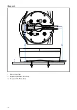
Страница 40: ...Rear exit 1 Mounting surface 2 Power and RayNet connectors 3 Power and RayNet cables 40...
Страница 42: ...42...
Страница 52: ...52...
Страница 53: ...Chapter 9 System connections Chapter contents 9 1 Typical system examples on page 54 System connections 53...
Страница 58: ...58...
Страница 59: ...Chapter 10 Power connections Chapter contents 10 1 Radar power connections on page 60 Power connections 59...
Страница 64: ...64...
Страница 69: ...Chapter 12 Operation Chapter contents 12 1 Operation instructions on page 70 Operation 69...
Страница 80: ...80...
Страница 84: ...84...
Страница 88: ......
Страница 91: ......


