background image

Wuhan Raycus Fiber Laser Technologies Co., Ltd.

User Guide of RFL- RFL-C3000S

33

5 Alarms and Solutions

5.1 Alarms Display

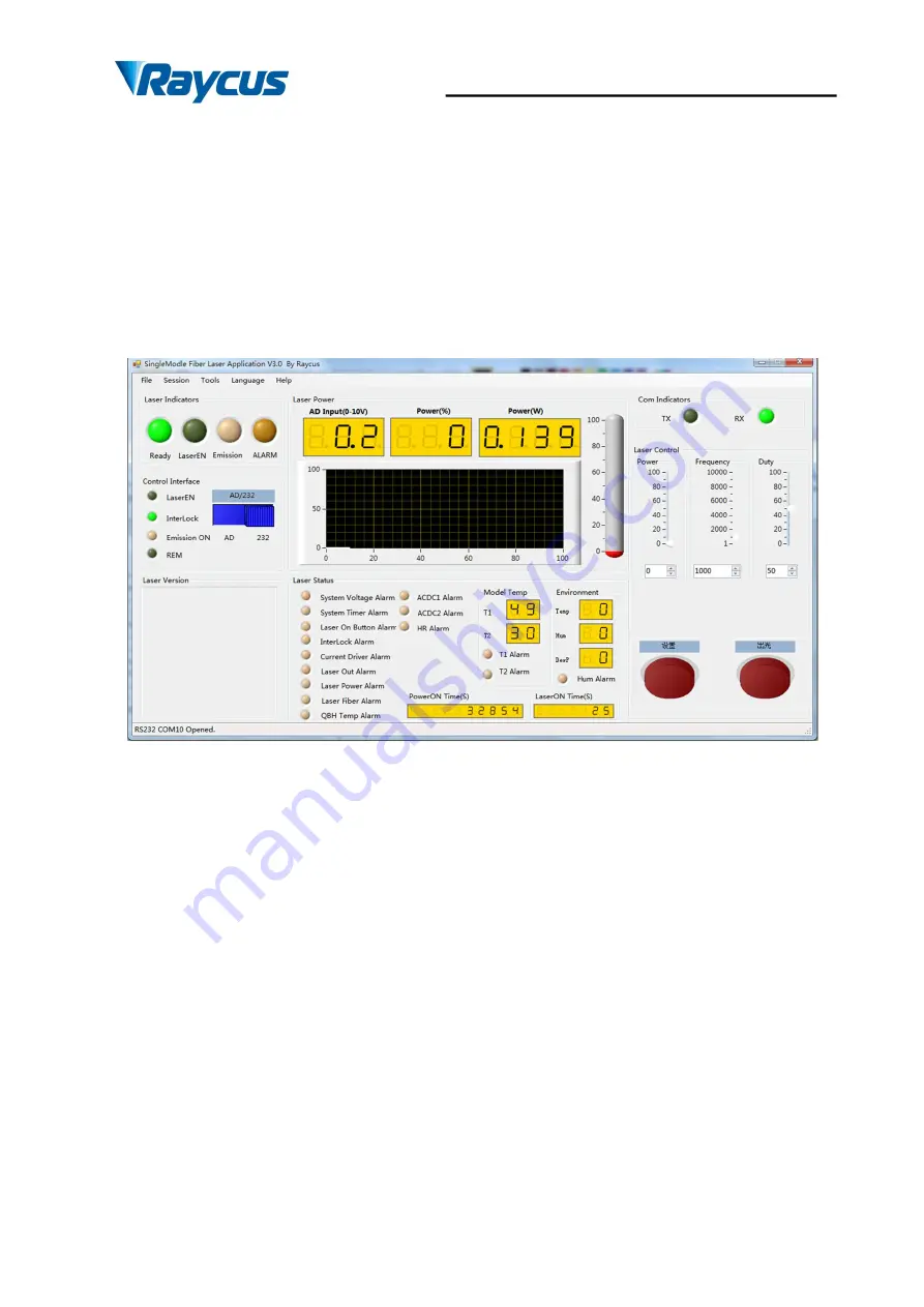
When the laser establishes communication with the client software,all alarm states of the

laser can be displayed on Raycus software homepage,as shown in Figure 1615(Download the

Rsycus software and software manual, please log in to Raycus official website)

Figure 16

The

homepage of Raycussoftware

If any alarm occurs (except for Interlock alarm)when the laser is running, the homepage will

display the alarm that occurs, and the ALARM light (yellow) on the front panel of the laser will

light up, the laser will stop emitting and lock.

When the Interlock is abnormal, the output of Ready signal is low, and the Interlock state is

abnormal in the software homepage, but the laser is not locked, and the ALARM light (yellow)

is not lit. Theoutput of Ready signal is on high level when the Interlock is normal.

5.2 Alarm solutions

The instructions and solutionsof alarms are as follows:

Содержание RFL-C3000S

Страница 1: ...1 Continuous Wave Fiber Laser User Guide RFL C3000S Wuhan Raycus Fiber Laser Technologies Co Ltd ...

Страница 2: ...n Environment 9 2 6 Precautions for Use 10 2 7 Specifications 11 3 Installation 12 3 1 Dimensions 12 3 2 Output Head and Installation 13 3 3 Cooling Requirements 14 3 4 Installation Procedure 16 4 Using the Product 18 4 1 Front Panel 18 4 2 Rear Panel 19 4 3 Power Connection 20 4 4 Interface Definitions 21 4 5 Steps of Installation 25 4 6 Steps of Starting 25 4 7 Control Modes 26 4 8 Steps of shut...

Страница 3: ...h CAUTION Refers to potential a hazard that may leads to aminorpersonal injury or product damage 1 2 Laser Classification This series of lasers are classified as a high power Class 4 laser instrument according to the European Community standards EN 60825 1 clause 9 This product emits invisible laser radiation at or around a wavelength of 1080 nm and the total light power radiated from the optical ...

Страница 4: ...ight emitted by the device over its entire range of wavelengths Please verify that the personal protective equipment e g enclosures viewing windows or viewports eyewear etc being utilized is adequate for the output power and wavelength ranges listed on the product 1 3 Safety Labels The position of the safety labels on products varies depending on the model of the continuous wave fiber laser as sho...

Страница 5: ...ifications of Safety Labels Take 500W for example 1 Aperture Label 2 Class 4 Laser Product 3 Class 2M Laser Product Label for Guide Laser 4 CE Compliance 5 Identification Plate 6 Laser Radiation Hazard Label 7 Electrical Hazard 1 4 Optical Safety Any dust on the end of the collimator assembly can burn the lens and damage the laser CAUTION If the output of the device is delivered through a lens wit...

Страница 6: ...oltage could damage the product 1 6 Other Safety Rules 1 Never look directly into the laser output port when power is supplied to the laser 2 Avoid using the laser in a dim or darkened environment 3 If this device is used in a manner not specified in this document the protection provided by the device may be impaired and the warranty will be voided 4 There are no operator serviceable parts inside ...

Страница 7: ...sily inserted into user s apparatus Main Features Excellent beam quality High quality fiber output High Power Stability Continuously tunable output power quick switching response Maintenance free operation High wall plugefficiency Convenient control interface High frequency modulation Applications Cutting Welding 3D Printing Scientific research 2 2 Model Configuration The series of Raycus continuo...

Страница 8: ...is shipped in a package designed to provide maximumprotection Upon delivery please inspect all packaging for evidence of mishandling or damage If you find any evidence of mishandling please save the damaged material and contact the shipping agent and Raycusimmediately Remove all the contents from the packing case Take extra care when removing the unit out of the packing case to ensure that thefibe...

Страница 9: ...Installation Requirements Install on flat surface no vibration or impact Ambient Temperature 10 40 Relative Humidity 30 70 Warning 1 Ensure reliable grounded before using the laser 2 The laser output is connected to the output cable Please check the laser output carefully to prevent dust or other contamination Use special paper when cleaning the laser output lens 3 If the laser is used in accordan...

Страница 10: ...e Failure to connect power source correctly will damage the device 2 Failure to follow the instructions may cause malfunction and damage to the device such damage is not covered by warranty 3 It is very important to ensure the cleanness of the calibrated laser output head otherwise it will cause irreparable damage to the laser 4 Please inspect the output head carefully for dust or other contaminat...

Страница 11: ...Output Power Operation Time 5h Ambient Temperature 22 1 Modulation Frequency Hz 1 5 000 Nominal Output Power Red Guide Laser Power mW 0 5 1 Optical Output Characteristics of QBH head Beam Quality mm mrad 1 5 2 Nominal Output Power Fiber Core Diameter μm 50 with 100 200 options Numerical Aperture 0 2 Delivery Cable Length m 20 Length customizable Electrical Characteristics Power Supply 380 10 V AC ...

Страница 12: ...12 3 Installation 3 1 Dimensions Figure 22 shows dimensions of RFL C3000S Figure 2 a Front panel view of RFL C3000S unit mm Figure2 b Rear panel view of RFL C3000S unit mm ...

Страница 13: ...Wuhan Raycus Fiber Laser Technologies Co Ltd User Guide of RFL RFL C3000S 13 Figure2 c Top and Side view of RFL C3000S unit mm 3 2 Output Head and Installation Figure 3aDimensions of QBH Output Head ...

Страница 14: ...assemble the output head by personnel not approved by Raycus or the warranty is void 3 3 Cooling Requirements Table 7 Cooling Requirements Model RFL C3000S Cooling Capability W 10000 Minimum Flow L min 22 Maximum Pressure Bar 7 Pipe Inner Diameter mm 19 Water temperature of coolingsystem 22 1 1 The water temperature setting of cooling system 22 1 RFL C3000S 2 Cooling water requirements It is recom...

Страница 15: ...ter 6 inner diameter 4 Direction of cooling liquid unidirectional connect the tube with the water pipe strictly according to direction shown on the layer of the tube Type of liquid de ionized water condensed water pure water PH value of liquid 5 5 9 Filter is needed for the cooling system and the size of the solid residual practicals should be within 100um Maximum temperature of liquid 45 Minimum ...

Страница 16: ... damage to the equipment CAUTION Make sure that the water temperature reaches the set point and the cooling system is working well before you start the laser summer 22 1 RFL C3000S winter 22 1 3 4 Installation Procedure 1 Place the product inan still and stable position 2 Check if the power supply has the correct voltage See Table 5 for the laser model and corresponding input voltage and the earth...

Страница 17: ...of the output fiber cable of the laser should not be less than 20 cm under the non working conditions and the minimum bending radius should not be less than 30 cm when the laser is working CAUTION All the cables can only be connected when power supply is OFF Hot plug may damage the laser CAUTION The laser output optical cable should be kept as natural as possibleand not be distorted The too small ...

Страница 18: ...f RFL C3000S 1 REM OFF ON Key switch the power switch of the laser Insert the key either turning the key clockwise to the ON position or counterclockwise to REM position will power on the laser Then the laser will enter a control mode depending on your previous setup on the CTRL INTERFACE You can refer to4 6 Control Mode for more details 2 POWER PowerIndicator GREEN indicates that the power is swi...

Страница 19: ...own position turn it clockwise to release but the laser cannot start before it s powered on with key switch for a second time 4 2 Rear Panel Figure 6 shows the rear panel of RFL C3000S Figure 6 Rear Panel of RFL C3000S 1 AC INPUT The socket for supply source input that can only be mated with the plug on the power cord we provided 2 POWER Air switch to control the switching of AC 3 CTRL INTERFACE C...

Страница 20: ...ggested the temperature of CDA is 5 below the temperature of cooling water The pressure of CDA is below 0 1MPa the flow rate is 10 LPM and the outer diameter of pipe mated with the connector is 6mm If the CDA filter module provided by Raycus is used the CDA should be also cooled and dried by the dryer and the pressure should be below 0 8MPa the outer diameter of pipe mated with the connector is 6m...

Страница 21: ... preventing After inserting it lock it with the lever 4 4 Interface Definitions 4 4 1 CTRL INTERFACE Definitions The CTRL INTERFACEis for laser control the designation and definition is below Figure 7CTRL INTERFACE Table 9 Definitions of 24 pin Ctrl Interface PIN No Name LineMark Type Level Drive Current Typical Response Time Description 11 NULL Contact Closure Input 5VDC 1A 500ms Drycontactspair ...

Страница 22: ...turn Return for signal on pin 15 17 EXTVCC EVCC Source Input 24VDC 100mA 1ms E x t e r n a l S o u r c e I n p u t 18 Emission Enable LAS C Digital Input 24VDC 6 mA 1ms Positive edge activates emission in REMOTE mode 19 READY RDY Digital output 24VDC 100mA 120ms High Laser is ready 20 System Common EGND Return Return for pin 17 18 19 21 21 AD RS AD RS Digital Input 24VDC 6 mA 120ms In REMOTEmode c...

Страница 23: ...e laser is powered on Caution Service Security Interface should not connect to any active signal or the interface will be damaged and the laser will report error 4 4 3 TCP IP Interface Configuration Thedefault IP address of this product is 192 168 0 10 only supporting UDP communication The laser listens for connection on port is 8098 and the command must be sent in a single data string Table 10The...

Страница 24: ...ftware to control the laser you need to find the folder where the Raycus software is located open the laser configuration file config xml and write the newly laser IP address If you do not use Raycus software please go to step 4 Step 4 Configure TCP IP select Use the following IP address manually assign an IP address and the IP address of your computer must be in the same network segment as the la...

Страница 25: ...ocessing equipment according to the actual situation install the output head cooling water pipe at the same time pay attention to the output cable and head then remove the protective cap andconfirm that the output lens is clean and install the output head 4 Connect cooling water pipe 5 Connect the control line and power according to the control mode 4 6 Steps of Starting All electrical connections...

Страница 26: ...ed In order to avoid damage the laser caused by condensation when the working temperature and relative humidity of the laser are in the dew point area the blue area in Table 4 for RFL C3000S please wait for the air conditioner to runfor 30 minutes before operate the laser later and for RFL C100 RFL C1000 please improve the working environment 4 Let the chiller work Turn on the key switch and start...

Страница 27: ... for 10s until the internal main control board circuit initialization is completed 7 Set the power of the laser the power is set by 0 10V analog single when the AD mode is enabled and the power is set by the PC software when the AD mode is disabled 8 Press the Laser button enable hardware emission on the front panel 9 Send the start or stop emitting command to control the emission via RS 232 See 4...

Страница 28: ... key switch to the REM position or turn the key switch to OFF short the SERVICE interface PIN 2 3 and the Power indicator on the front panel light on 6 Wait for 10s until the internal main control board circuit initialization is completed 7 Set the power of the laser the power is set by 0 10V analog single when the AD mode is enabled and the power is set by the PC software when the AD mode is off ...

Страница 29: ...s applied to 24V the laser enters the external AD mode and the power of the laser is controlled by the voltage obtained by PIN12 13 1V 10 power 10V 100 power When PIN 20 21 is applied to 0V or left floating the power of the laser is set by serial port or Ethernet 4 7 5 Control sequence diagram Figure 11Control sequence diagram of CW mode ...

Страница 30: ...30 Figure 12 Control sequence diagram of Pulse mode Figure 13 Control sequence diagram of External AD mode ...

Страница 31: ... on the laser POWER green indicator is illuminated and thered guide laseris output The red guidelaser is off when LASER button in front panel is pressed down or command EMON is sent via RS 232 while the red laser is on when LASER is released or command EMOFF is sent via RS 232 CAUTION The red laser and the laser emission cannot be output at the same time If there is no red light output please chec...

Страница 32: ...switch to the OFF position and release LASER button 3 Turn off the chiller 4 If the product have air conditioner please waiting10 minutes for the air conditioner to continue working If the laser does not have air conditioner please ignore this step 5 Disconnect the air switch 6 Cover the output head protection cap ...

Страница 33: ...page of Raycussoftware If any alarm occurs except for Interlock alarm when the laser is running the homepage will display the alarm that occurs and the ALARM light yellow on the front panel of the laser will light up the laser will stop emitting and lock When the Interlock is abnormal the output of Ready signal is low and the Interlock state is abnormal in the software homepage but the laser is no...

Страница 34: ...r Alarm this error occurs when the constant current driver board inside the laser is abnormal Solution Restart the laser If this error continues to occur please contact Raycus Laser Out Alarm Instruction 1 Laser Out Alarm immediately occurs when the laser is powered Solution The laser will autolock after two times of this error occurs successive please contact Raycus 2 The laser will get this erro...

Страница 35: ...oling system is normally working the water temperature is set correctly and the water connection is correct When the water cooling system works normally and the water temperature drops below 30 C restart the laser If the alarm continues please contactRaycus Low temperature alarm please check if the actual water temperature of the water is too low In addition a low ambient temperature may also caus...

Страница 36: ...36 continues to occur please contact Raycus In addition to the above if there are any questions or errors inusing of the laser you can contactRaycus to get help ...

Страница 37: ...tenance damages caused by those who are not from Raycus due to excessive use or not following the instructions Customer has the responsibility to understand and follow this instruction to use the device Any damage caused by fault operating is not warranted Accessories and fiber connectors are excluded from this warranty According to the warranty client should write to us within 31 days after the d...

Страница 38: ...any of our products at anytime without incurring any obligation to make changes or install the same on units previouslypurchased All the items about warranty and service above provided by Raycus are for user s reference formal contents about warranty and service are subject to the contract 2019 Wuhan Raycus Fiber Laser technologies Co Ltd All Rights Reserved ...

Отзывы: