www.raycap.com
Installation Instructions:
2260-ALM-RS485
INSTALL INSTRUCTIONS
Страница 1: ...www raycap com Installation Instructions 2260 ALM RS485 INSTALL INSTRUCTIONS 2260 ALM RS485 ...
Страница 2: ......
Страница 3: ...ycap welcomes customer comments as part of the process of continuous development and improvement of the documentation This product is suitable for OSP Raycap has made all reasonable efforts to ensure that the instructions contained in this document are adequate and free of material errors and omissions Raycap will if deemed necessary explain issues which may not be covered by this document The con...
Страница 4: ...tes This document describes the steps to achieve communication link from an existing 6 OVP RM at the base to the newly installed 12 OVP RVZDC 6627 PF 48 at top of the tower Installers of Raycap s RRH surge protective and fiber power management solutions must be industry professionals who have attended training on the proper installation of the equipment by Raycap and or the mobile operator Install...
Страница 5: ...wing step by step instructions will lead you through the installation process Installed cables and wires not shown for clarity 4 1 WARNING Disconnect or disable the DC power source to the product prior to beginning this installation 4 2 Remove 4 screws securing touch guard shielding to access power cables Set touch guard and screws aside 4 3 Make note of each cable connection to ensure proper conn...
Страница 6: ...his touch guard will not be used when installing the 2260 ALM RS485 kit 4 5 Make note of each wire connection to ensure proper connections are established when reinstalling alarm wires ATTENTION Electrostatic sensitive devices ESD mitigative procedures such as wearing wriststraps are to be used during installation and maintenance Remove alarm wires from ALL terminals Touch Guard over PCB Alarm Ter...
Страница 7: ...NS 2260 ALM RS485 4 6 Remove the 4 stand offs using a 1 4 nut driver and set aside 4 7 Remove the 4 Philips head screws securing the PCB and set aside 4 8 Slide PCB down to disconnect from front PCB 4 9 Disconnect ribbon cable from PCB 4 10 Remove PCB and set aside This will not be reused ...
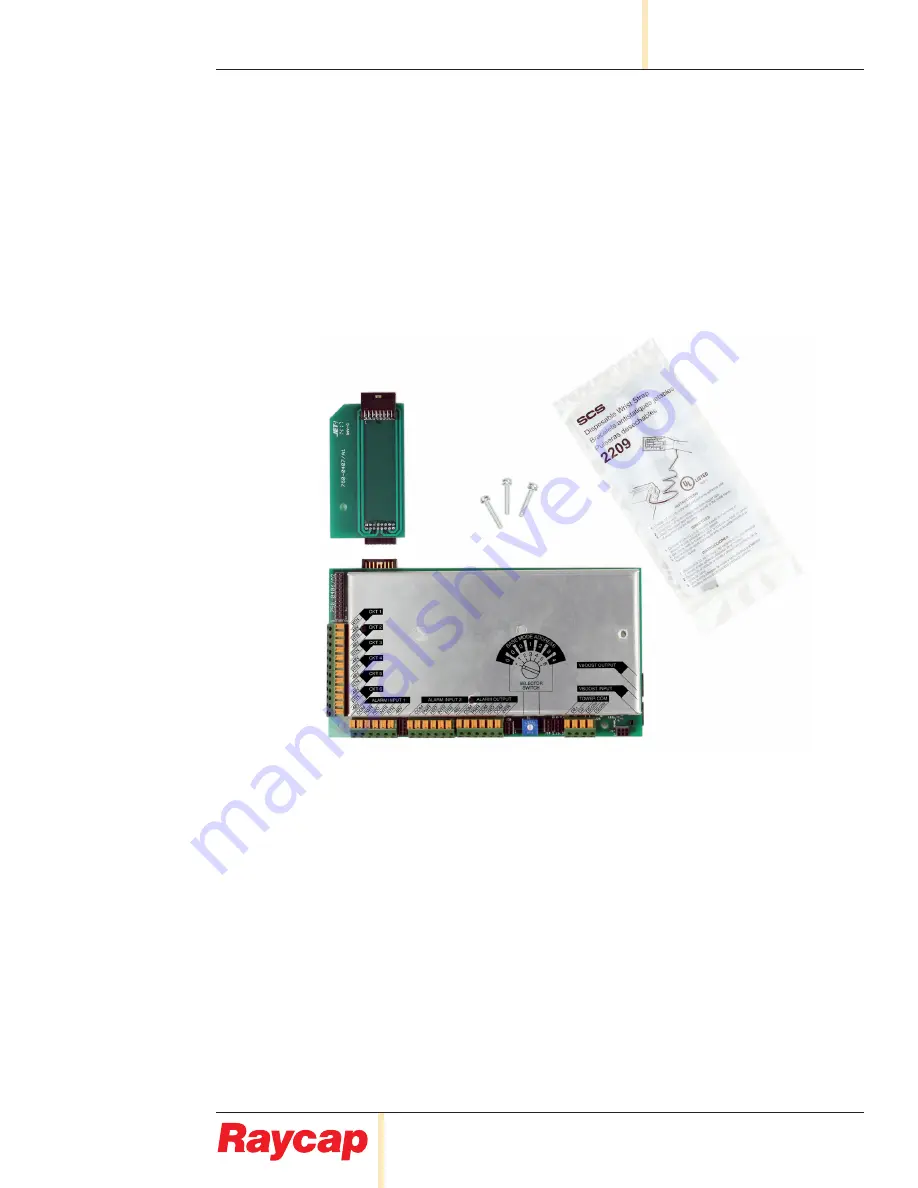
Страница 8: ...rved 320 1254 Rev C Page 8 of 24 2260 ALM RS485 INSTALL INSTRUCTIONS Procedure 5 0 Installing the PCB Retrofit Kit 5 1 Remove Alarm Inputs label from unit The next step will mate the intermediate PCB to a blind connection in this location ...
Страница 9: ...tallation Orientation Chamfer Connector up Screw hole 5 2 Slide Intermediate PCB up to connect to front PCB Ensure Intermediate PCB is Correctly Aligned and fully seated new shrouded connecter aides in blind connection Reassemble unit with new PCB as follows 5 3 Secure the intermediate PCB using the 1 small screw ...
Страница 10: ...ed 320 1254 Rev C Page 10 of 24 2260 ALM RS485 INSTALL INSTRUCTIONS 5 4 Connect main PCB to intermediate PCB Ensure 2260 ALM RS485 PCB is Correctly Aligned see below and fully seated Correctly Aligned Incorrectly Aligned Incorrectly Aligned ...
Страница 11: ...INSTALL INSTRUCTIONS 2260 ALM RS485 5 5 Ensure screw holes in the frame line up to holes in the PCB and install the reuse 2 small screws Install the 3 long screws to secure PCB 5 6 Reattach ribbon cable to new PCB Red stripe should be closest to the CKT 1 return connector ...
Страница 12: ...www raycap com Raycap All rights reserved 320 1254 Rev C Page 12 of 24 2260 ALM RS485 INSTALL INSTRUCTIONS 6 0 Installation Complete ...
Страница 13: ...2 For Daisy Chain D Alarm Output to BTS Outputs for Intrusion H2O and Power E Rotary Switch for Base Mode Operation Place rotary switch to position 1 or 2 which corresponds to base mode address 0 If in daisy chain configuration place selector switch to the next base mode address F Base Communication Base RS485 communication input from tower 2 twisted pair 4 wires total G VBoost Input Optional ethe...
Страница 14: ...onnections for 2260 ALM RS485 RVZDC 6627 PF 48 at the Tower Top connected to 2 RVZDC 2260 RM 48 with Retrofit Kits at the base This wiring scenario will be almost identical to 2 base located RVZDC 3315 PF 48 units with Retrofit Kits Tower Pair Color Data 1 Black D2 White Black D2 2 Orange REF2 Orange Black REF2 3 Violet D1 Violet Black D1 3 Yellow REF1 Yellow Black REF1 ...
Страница 15: ...Rev C Page 15 of 24 INSTALL INSTRUCTIONS 2260 ALM RS485 Alarm Outputs to BTS Note Selector switch set to 3 for Base mode address 1 Note Selector switch set to 2 for Base mode address 0 Daisy Chain Output to next Base unit Daisy Chain Input Base 0 Base 1 ...
Страница 16: ... to RVZDC 2260 RM 48 with a retrofit kit at the base Note The diagram shows the color code for the hybrid cable used between the tower top unit and the rack mount unit Hybrid Cable 4 Voltage monitor Pairs PCB TERMINAL BLOCK DISTRIBUTION UNIT 1 2 3 PCB TERMINAL BLOCK 4 5 6 PASS THRU CIRCUITS 4 6 RTN 1 48V 1 RTN 2 48V 2 RTN 3 48V 3 RTN 4 48V 4 RTN 5 48V 5 RTN 6 48V 6 PASS THRU CIRCUITS 1 3 R T N 4 8...
Страница 17: ...ecting the alarms for the Raycap products Voltage monitoring circuit on previous page Wire the alarms using the Verizon approved color code COM 48V PWR H20 INTR SP2 SP1 COM RTN INTR H20 PWR 2 OUTPUT TO BASE OVP 1 5 4 3 ALARM INPUT 3 RTN INTR H20 PWR 48V COM COM 6 1 6 MAIN OUTPUT TO BTS 2 3 4 5 1 2 3 4 5 6 ALARM INPUT 2 ALARM INPUT 1 1 2 3 4 5 6 6 5 PWR H20 INTR RTN 48V 4 3 2 1 TOWER TOP OVP UNIT R...
Страница 18: ... rights reserved 320 1254 Rev C Page 18 of 24 2260 ALM RS485 INSTALL INSTRUCTIONS 7 4 Meaning of signal lights Right and left center bars flashing bootloader mode Lower left bar flashing reciept varification of daisy chain data ...
Страница 19: ...m Raycap All rights reserved 320 1254 Rev C Page 19 of 24 INSTALL INSTRUCTIONS 2260 ALM RS485 Lower right bar flashing reciept and varification of tower data Upper right bar flashing Analog packet generated at base ...
Страница 20: ...ration Supported Base Unit 1 Tower 1 Tower 2 6627 6627 NONE YES 6627 3315 with Retrofit NONE YES 6627 3315 with Retrofit 3315 with Retrofit YES 6627 6627 6627 NO 6627 6627 3315 NO 6627 12 OVP Dome 3315 6 OVP Dome with Retrofit Retrofit Alarm Board installed 6 OVP Rack Dome Configurations Base Unit Connected at Base Unit Connected at Top Configuration Supported Base Unit 1 Base Unit 2 Tower 1 3315 ...
Страница 21: ...www raycap com Raycap All rights reserved 320 1254 Rev C Page 21 of 24 INSTALL INSTRUCTIONS 2260 ALM RS485 Notes ...
Страница 22: ...www raycap com Raycap All rights reserved 320 1254 Rev C Page 22 of 24 2260 ALM RS485 INSTALL INSTRUCTIONS Notes ...
Страница 23: ......
Страница 24: ...www raycap com Raycap All rights reserved 320 1254 Rev C Page 24 of 24 2260 ALM RS485 INSTALL INSTRUCTIONS ...