37
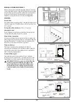
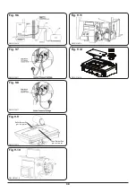
REMOVAL OF TRANSPORT SCREW/S
Remove the hotplate and boiler top plate. Remove retaining
screws from boiler plates. Check that all plates have remained
in their correct position and that no debris has accumulated
on them during transport. Replace boiler top plate and
hotplate ensuring that all seals are intact (See
FUNCTION
Normal Start
Pre-ignition and pre-purging, after 7 seconds oil released, and
the burner operates, if the flame forms within the safety time
of 10 seconds.
Post ignition after oil release:
LOA 24 - 10 seconds.
False light at start
If oil is released and no flame is established the control will
cut out within the safety time of 10 seconds.
Flame failure in operation
In the event of flame failure in operation the oil supply is cut
off and the control restarts the burner as described under the
heading “Normal Start”. On flame failure, immediately after
burner start, the control will initiate re-ignition.
Flame monitoring
The flame is monitored by a photocell unit. Note: In
accordance with the latest ISO and DIN standards, type LOA
activates the safety relay if the photocell unit is exposed to
light in the pre-purging period.
Control of flame signal
The photocell current is measured with a d.c. ammeter
(moving coil instrument) which is connected in series with
the photocell unit. Min current for flame indication: 35 μA.
n
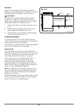
IMPORTANT NOTE: Once you are satisfied that the
cooker is properly installed in accordance with
these instructions, you must turn off the cooker
which should not be re-lighted until it has been
commissioned by an accredited Commissioning
Agent.
RAYBURN
HEATRANGER
RAYBURN
HEATRANGER
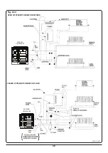
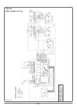
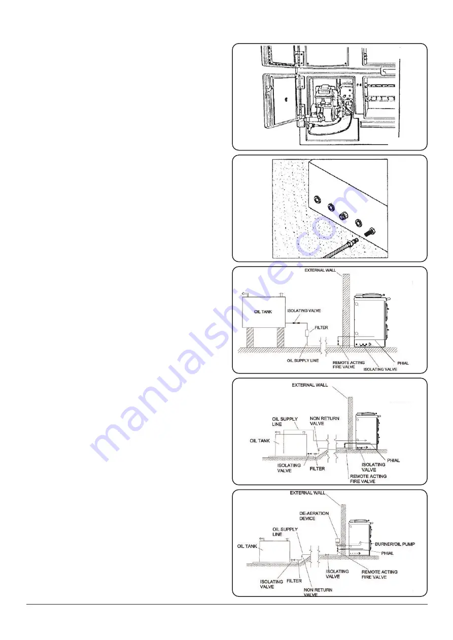
Fig. 9.1
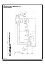
Fig. 9.2
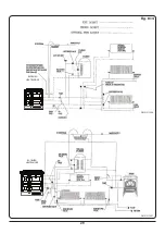
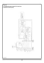
Fig. 9.4
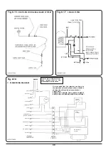
Fig. 9.5
RAYBURN
HEATRANGER
RAYBURN
HEATRANGER
RAYBURN
HEATRANGER
DESN 518005
DESN 518006
DESN 518007
DESN 518008
DESN 518009
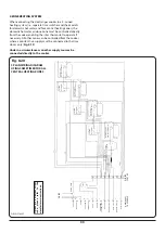
Fig. 9.3

