36
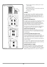
fitted close to the burner and is linked to the tank by a single
pipe, thus saving the return pipe required by the two pipe
system as described previously. Any air in the oil brought up
from the tank is bled off in the de-aeration chamber.
De-aeration chambers must always be installed externally to
buildings because they emit small quantities of vapour. The
chamber is connected to the oil pump in the burner of the
appliance by a normal two pipe loop.
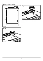
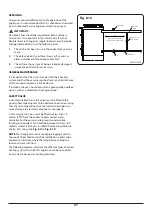
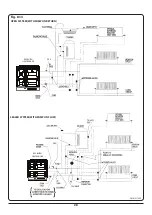
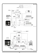
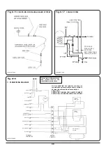
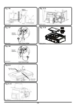
TIGER LOOP OIL SUPPLY (see
)
For installations normally requiring a two pipe system but
have long or difficult return line runs, an alternative Tigerloop
Deaerator system can be used. Tigerloop Deaerators remove
air from a two pipe oil feed. Higher lift heights can be
achieved than are possible with a conventional two pipe
system.
These requirements are fully explained within the following
documents:
•
B.S. 5410: Part 1: Code of Practice for Oil firing
installations up to 45 kW output capacity for space
heating and hot water supply purposes.
•
OFTEC - Technical Information Book Three. Installation
requirements for oil fired boiler and oil storage tanks.
•
The Building Regulations Part J: Ireland Part F Section 4
Scotland and Part L Northern Ireland.
•
The Building Regulations Part J: England & Wales.
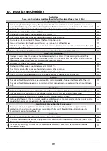
INSTALLATION CHECK LIST
1.
Check all items from packaging are removed from ovens
and the shelves are properly fitted.
2.
Check that electrical wiring is correct.
3.
Check that the boiler and heating system is full of water
and purged of air.
4.
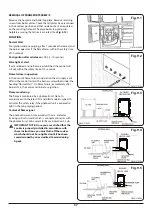
Check that the boiler plate transport screws have
been removed and that the plates are in their correct
positions. (See section removal of transport screw and
)
5.
Time switches and room thermostats must be on.
6.
Check that all valves in the oil line are open and that the
filter is purged of air. Check that the fire valve is open.
7.
Turn on the electrical supply and check that any time
switches are on and room thermostats associated with
the cooker are on and calling for heat. Burners should
now fire.
8.
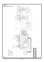
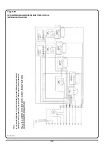
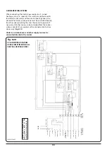
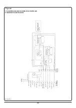
Check that the interstat connection has been wired
directly to a motorised valve. This is done by turning
off room thermostats, time switches and temporarily
linking terminals 6 & 9. This should bring on a motorised
valve which will then call the boiler. Note: When the
interstat calls; normally the motorised valve will open,
but the burner will not operate as the supply to No.6
will be disabled.
9.
Check temperature differential between flow and return
11°C (20°F) and adjust pump or bypass accordingly.
10.
Check heating circuit and balance if necessary.
11.
With fuel supply off, switch on the burners.
12.
Complete the start sequence to lockout (8 seconds) for
both burners observing the correct operating functions.
13.
Ensure both pumps are purged of air. Check pump
pressure with a calibrated pressure gauge and adjust
it as necessary. (See
) For further
information refer to 100, 80 and 60 specification on
14.
14. Re-instate fuel supply and switch on the burners to
ensure that they fire correctly.
15.
After the appliance has achieved its operating
temperature, with each burner running, carry out a flue
gas analysis for each burner. (See
16.
Check for smoke and flue draught reading.
17.
Check and set combustion approximate settings:
Boiler
Cooker
Air Setting
CO2%
Air Setting
CO2%
9
11.5
5
10
8
11.8
4
10.34
7
11.9
3
10.8
6
12.2
2
11.2
18.
Find the correct position of the air control, which gives
the highest reading of CO2 within the range of the table
above without exceeding a smoke No. 0-1 (Bacharach
Scale). (See
&
19.
Check the oil supply for leaks from storage tanks via oil
filter.
20.
Check if complete system is working correctly.
21.
Make sure specified clearances are adhered to.
22.
Check flue joints are sealed correctly and that no
escapes are present.
23.
If not satisfied check the trouble shooting guide.
24.
After withdrawing the mains cable tighten the anti-tug
gland located at the left side of the cooker base level.
25.
Refer to the Operation Instructions Manual for correct
operation of the appliance and familiarise the occupants
on the correct method of operating the appliance.
LEAVE ALL DOCUMENTS WITH THE END USER.
26.
Check lockout (8 seconds)
a.
Check cooker burner is purged of air, check cooker
burner with a calibrated pressure gauge and adjust if
necessary to 110 p.s.i.
b.
To complete commissioning exercise refer back to
point number 14.

