Commissioning
ELECTRICAL INSTALLATION
WATER CIRCULATION SYSTEM
COMMISSIONING THE COOKER
AND BOILER
INSTRUCT THE USER
LIGHTING THE BOILER BURNER
BOILER OUTPUT SETTING
BOILER COMBUSTION
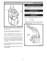
Fig. 20
DESN 514873
19
Checks to ensure electrical safety should be carried out
by a competent person i.e. earth continuity, polarity and
resistance to earth.
The whole of the system should be thoroughly flushed
out with cold water without the pump in position. Ensure
that all valves are open. With the pump fitted, the system
should be filled.
Vent all heat emissions and check for water soundness.
Insert condensate trap.
Isolate electricity supply at the wall socket. Turn the
cooker and boiler control knob to off.
After ensuring gas is available to the appliance, loosen
joint and purge any air from the supply pipe.
WARNING: NO SMOKE OR NAKED LIGHTS.
Tighten joint and check gas service cocks are in the ON
position. Check for gas soundness up to the gas valves.
1.
Advise the User of the precautions necessary to
prevent damage to the heating system and to the
building in the event of the heating system being
inoperative during frost conditions.
2.
Advise the User for continued efficient and safe
operation of the appliance. It is important that
adequate servicing is carried out at regular 12
monthly
intervals.
3.
Hand the Users Instructions to the User and
demonstrate the correct operation of the appliance
and system controls.
4.
Leave the Installation, Servicing and Users
instructions with the User.
5.
Gas Safety -
Show the user the procedure for
isolating the appliance from the gas and electric
supply. As referred to in the Users Instructions - Ref.
Gas Leak or Appliance Fault.
To light the burner - turn the boiler thermostat to maximum
and create a demand on the room thermostat.
Check the gas consumption and ensure it is ±5% of the
nominal, 26.7 kW.
Connect a suitable analyser to the flue outlet of the boiler.
(See Fig. 20).
Although the appliance is pre-set check that the CO
2
/CO
levels are within tolerances.
CO
2
8.8 - 10.2%
CO
0-50ppm
To check the levels at full rate, turn the boiler knob fully
clockwise.
To check the levels at the low rate, turn the boiler knob to
the first segment of the dial.
If these levels are within the tolerance, no further action is
required with the boiler.
If levels are not within tolerance check for possible causes
e.g. blocked flue, faulty fan etc. If non other fault can be
detected, the gas valve needs to be adjusted manually.
To do this, turn the boiler knob fully clockwise to create
the highest possible demand.
Turn the gas valve regulator A (See Fig. 21) in the
appropriate direction. Turning clockwise will decrease the
CO
2
turning anti-clockwise will increase the CO
2
. Please
note that due to the sensitivity of the screw, only small
adjustments will be necessary.
Содержание Heatranger 480CD
Страница 13: ...Installation Instructions 13 Fig 9 ...
Страница 18: ...Sealed System Fig 19 18 ...
Страница 21: ...21 ...
Страница 22: ...22 ...
Страница 23: ...23 ...


