SITE LOCATION
1.
Remove the appliance assembly from the transit
wooden pallet by the temporary location of a sloping
ramp board between the pallet and the floor. With the
appliance on the floor, lift the front of the appliance
(manually or with a crowbar) and insert a 32mm x 1m
long tube between the front of the appliance base plate
and the floor.
Draw the tube balanced appliance forward until the
tube is at the rear of the appliance and then insert a
second similar tube at the front of the appliance
between the base plate and the floor. The tube
supported appliance can now be slowly “rolled” across
the floor and positioned with its back against the wall,
and in its intended position for flue connection.
Using a crowbar at the rear of the appliance base plate,
take the weight of the appliance on the crowbar and
remove the rolled tube, followed by similar action
on the front tube.
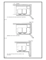
The appliance is floor mounted. The space in which
the appliance is to be fitted must have the following
minimum dimensions:
Between wall and LH side of appliance - 150mm
Between wall and RH side of appliance - 10mm*
*SHOULD THE WALL PROJECT BEYOND THE
FRONT OF THE APPLIANCE, WHEN IT MUST BE
INCREASED TO 50mm (SEE FIG. 2A, 2B & 2c)*
Above the raised insulating cover handle - 60mm
In addition the adequate clearance must be available at
the front of the appliance to enable it to be operated and
serviced.
The appliance is delivered assembled with the exception
of the following items, which are supplied separately
packed and require assembly.
1. Air Inlet Spigots/Concentric Balance Flue Kit
2. Appliance Rear Distance Bracket - (for use when
appliance is installed (25mm) away from a rear
wall of combustible material). See Fig. 5.
3. Handrail - The handrail brackets are held on the
front ends of the cooker top-plate casting. Remove
the travel nuts and replace with the handrail brackets
ensuring the fibre protecting washers are in position.
Insert the handrail with fitted endcaps in to the brackets,
positioning them correctly, and tighten the locating bolts.
(See Fig. 6).
Installation Instructions
10
CLEARANCES
PRELIMINARY INSTALLATION
Fig. 5
DESN 512553
Fig. 6
DESN 510454 A
Содержание Heatranger 480CD
Страница 13: ...Installation Instructions 13 Fig 9 ...
Страница 18: ...Sealed System Fig 19 18 ...
Страница 21: ...21 ...
Страница 22: ...22 ...
Страница 23: ...23 ...


