


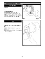


BEFORE REMOVING SERVICE ACCESS COVERS
ENSURE THAT ALL ELECTRICAL ACCESS TO THE
APPLIANCE HAS BEEN SWITCHED OFF (SWITCH
OFF AND REMOVE PLUG).
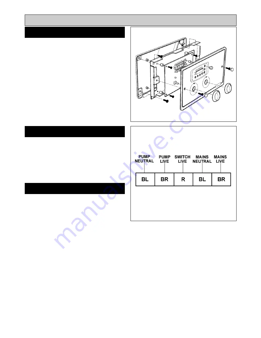
SEE FIG. 25
1.
Remove the controls door
(Rayburn 660/680/699K
only)
and place in a safe position.
2.
Remove both thermostat control knobs.
3.
Remove the 2 cover panel fixing screws.
4.
Remove glass cover panel and place in a safe
position.
5.
Remove the two control panel fixing screws.
6.
Pull open facia controls chassis (hinged on RH side)
and remove 3 pin plug from rear of control board.
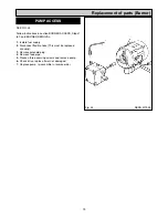
1.
Re-attach the 3-pin plug.
2.
Close facia controls chassis and secure with the 2
screws.
3.
Refit the outer panel in position and secure with the 2
screws.
4.
Replace the thermostat knobs.
5.
Replace the controls door
(Rayburn 660/680.699K
only)
.
SEE FIG. 26
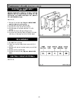
20
ELECTRICAL COMPONENT
ACCESS
Replacement of parts
(Electrical controls)
Fig. 25
DESN 515773
RE-ASSEMBLE
CONTROL CIRCUIT-EXTERNAL
Fig. 26
DESN 514865
Содержание 660
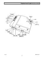
Страница 21: ...21 Fig 27 DESN 514774 Replacement of parts Electrical controls ...
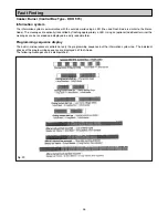
Страница 22: ...22 Fault Finding Fig 28 Rayburn 600 700 Wiring Diagram 111MB for Individual Satronic boxes ...
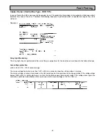
Страница 23: ...23 Fault Finding Fig 29 Rayburn 600 700 Wiring Diagram 111MB self contained control ...
Страница 29: ...Fault Finding 29 Fig 31A DESN 516838 ...
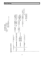
Страница 30: ...30 Fault Finding ...
Страница 31: ...31 Fault Finding ...
Страница 33: ...33 ...
Страница 34: ...34 ...
Страница 35: ...35 ...