CHAPTER
5
Manual No. 016-0171-079 Rev F
21
CHAPTER 5
TROUBLESHOOTING
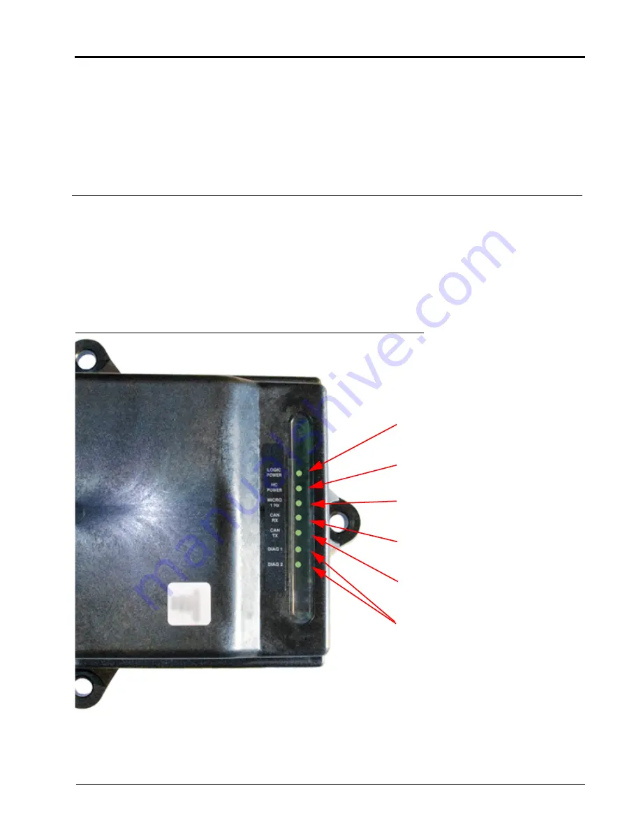
The AccuBoom CAN control node (P/N 063-0172-316) features several green light-emitting diodes (LEDs) which
may be used to diagnose issues within the AccuBoom system.
NOTE:
If the LEDs are not displayed as outlined in the figure below, check the CAN connections and the
control cable connections on the node. If the issue persists, contact your local Raven dealer for
additional technical support.
NOTE:
All boom switches must remain in the off position while AccuBoom control is in operation.
FIGURE 1. AccuBoom CAN Control Node LEDs
Logic Power - Lit when +12 V current
is supplied to the node.
HC (High Current) Power - Lit when
High Current Power is supplied to the
node.
Micro 1 Hz - Flashes once every
second during processor activity.
CAN Rx - Flashes to indicate CAN
messages are being received by the
node.
CAN Tx - Flashes to indicate CAN
messages are being transmitted from
the node.
Diag (Diagnostics) 1/2 - Currently not
used with the AccuBoom™ system.
Содержание SCS 460
Страница 2: ......
Страница 4: ...Table of Contents ii SpraCoupe 3000 4000 with SCS 460 Console AccuBoom Installation Manual ...
Страница 22: ...CHAPTER 3 18 SpraCoupe 3000 4000 with SCS 460 Console AccuBoom Installation Manual ...
Страница 24: ...CHAPTER 4 20 SpraCoupe 3000 4000 with SCS 460 Console AccuBoom Installation Manual ...
Страница 26: ...CHAPTER 5 22 SpraCoupe 3000 4000 with SCS 460 Console AccuBoom Installation Manual ...
Страница 28: ...Index 24 SpraCoupe 3000 4000 with SCS 460 Console AccuBoom Installation Manual ...


