background image

016-4010-001 Rev. F

85

SLINGSHOT

WiFi Channel 

- Displays the channel the WiFi hot spot is currently using. If the operator is experiencing a 

issues with connectivity or staying connected, adjusting these settings may improve connectivity issues. This 

setting can be modified by the operator. The WiFi password can only be modified through the Slingshot 

website.

MANUAL CLIENT

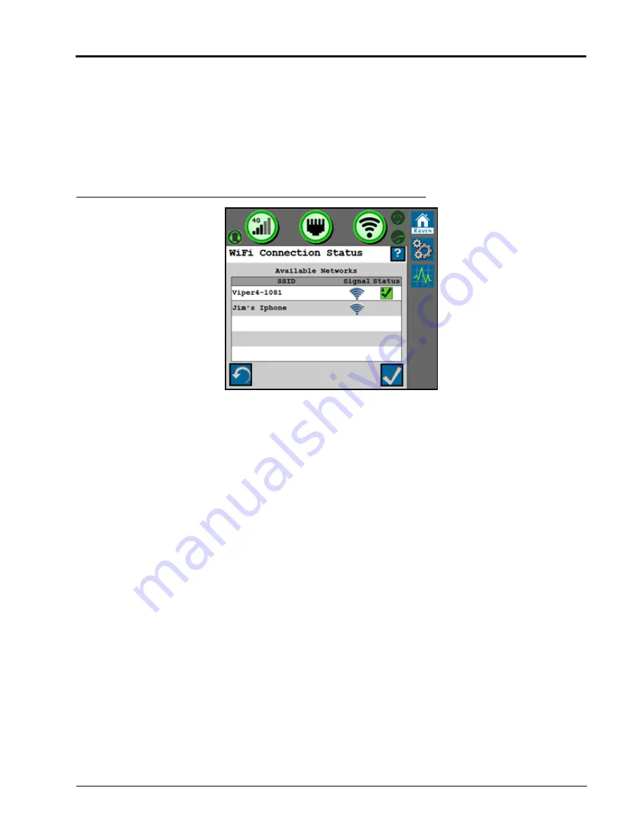
Select Manual Client to manually connect to available WiFi networks.

FIGURE 19. WiFi Connection Status

• Touch the refresh button in the lower, left corner to update the list of available WiFi networks.
• Select an available network to enter the WiFi password and connect to the selected network. The network to 

which the system is currently connected will display with a green check mark on the WiFi Connection Status 

screen.

MANUAL HOTSPOT

Select Manual Hotspot to broadcast a hotspot for local WiFi devices.

RAVEN AUTO

Select Raven Auto to allow the system to automatically select the best WiFi network connection. To change which 

WiFi network the system is connected to, select the Manual Client mode.

NOTE:

When set to Raven Auto, a small “A” indicator will be displayed to indicate Raven is controlling the 

Hotspot and WiFi settings for the system.

Содержание RS1

Страница 1: ...Copyright 2017 2018 2019 2020 Raven RS1 and RS Lite Calibration and Operation Manual 016 4010 001 Rev G 12 2020 E36462 ...

Страница 2: ...aven Industries shall not be held responsible for any modifications or repairs made outside our facilities nor damages resulting from inadequate maintenance of this system As with all wireless and satellite signals several factors may affect the availability and accuracy of wireless and satellite navigation and correction services e g GPS GNSS SBAS etc Therefore Raven Industries cannot guarantee t...

Страница 3: ...ction 7 RS1 Terms of Use 8 GPS and Steering Calibration 8 GPS Calibration 8 Terrain Compensation Calibration 13 Steering Calibration 16 Resume Disengage Calibration 16 Calibrate the Wheel Angle Sensor WAS 17 Calibrate the Machine Steering System 19 Chapter 4 Steering Home Screen 23 Chapter 5 Machine Settings 25 Chapter 6 Steering Setup 27 Advanced Tuning 28 Wheel Control Settings 30 Wheel Control ...

Страница 4: ... 48 Proportional Gain 49 PWM Min 49 PWM Max 49 Brake Settings 49 Chapter 9 Feature Unlock Codes 51 Chapter 10 Routine Operation 53 Widget Definitions 53 UT Navigation Buttons 54 Starting a Job 54 Engage Steering 54 Updating RS1 55 Chapter 11 Diagnostics and Troubleshooting 57 Button Definitions 57 Steering Status 57 Master Switch 58 Resume Switch 59 Disengage Sensor 59 Wheel Angle Sensor 59 Operat...

Страница 5: ...77 Field Updates 78 Remote Diagnostics 81 System Settings 82 Cellular Settings 82 Ethernet Settings 84 WiFi Settings 84 Manual Client 85 Manual HotSpot 85 Raven Auto 85 RTK Source Settings 86 Radio Configuration 87 Feature Unlocks 88 System Information 89 Diagnostic Trouble Codes DTC 91 Chapter 13 System Diagrams 93 Chapter 14 Roadway Homologation 97 Certification 98 Safety Notes 98 ...

Страница 6: ...Table of Contents iv Raven RS1 and RS Lite Calibration and Operation Manual ...

Страница 7: ...serve the following safety measures when operating the implement after installing this Raven system Do not operate this Raven system or any agricultural equipment while under the influence of alcohol or an illegal substance Be alert and aware of surroundings and remain in the operator seat at all times when operating this Raven system Do not operate the implement on any public road with this Raven...

Страница 8: ...ions to prevent foreign material or contaminants from being introduced into the implement hydraulic system Contaminants that are able to bypass the hydraulic filtration system will reduce performance and may damage hydraulic components Stand clear of the implement when starting the system for the first time after installing or servicing hydraulic components in case a hose has not been properly con...

Страница 9: ...or flame cut corners fastener threads or cap screw heads hose clamp ends etc Avoid areas where the operator or service personnel might step or use as a grab bar Do not connect affix or allow hoses to come into contact with components with high vibration forces hot surfaces or components carrying hot fluids beyond the temperature rating of hose components Hoses should be protected or shielded if ro...

Страница 10: ...nessing component specifications Avoid routing harnesses in areas where damage may occur due to build up of material e g dirt mud snow ice etc Avoid routing harnesses in areas where the operator or service personnel might step or use as a grab bar IMPORTANT Avoid applying direct spray or pressure washing of electrical components and connections High pressure streams and sprays can penetrate seals ...

Страница 11: ... specifically for the equipment before being used to operate the RS1 system Refer to the Operation Manual for the field computer used to operate the RS1 system Installation and Operation Manuals for Raven systems can be downloaded from the Raven website https portal ravenprecision com SYSTEM SPECIFICATIONS RS1 ELECTRICAL RATING The specifications below are specific to the RS1 system INSTALLATION B...

Страница 12: ... the machine looking toward the cab UPDATES Software and manual updates are available on the Raven Applied Technology website https portal ravenprecision com Sign up for email alerts and you will be automatically notified when updates for your Raven products are available on the website At Raven Industries we strive to make your experience with our products as rewarding as possible One way to impr...

Страница 13: ... Terminal on the display or field computer Guidance and Steering Allows the steering and GPS settings within the RS1 unit to be calibrated and modified Slingshot Allows the cellular Ethernet and WiFi settings within the RS1 unit to be modified Raven Guidance and Steering Working Set Icon Slingshot Working Set Icon Guidance and Steering Software Home Screen Slingshot Software Home Screen ...

Страница 14: ...steering partner is registered with the RS1 GPS AND STEERING CALIBRATION NOTE The System Information diagnostic trouble codes DTCs and Machine Test screens can be viewed during calibration For further information on these settings refer to the following sections of this manual System Information on page 67 Diagnostic Trouble Codes DTC on page 62 System Information on page 67 GPS CALIBRATION FIGURE...

Страница 15: ...nable Screen NOTE The AutoCart System page will only display when calibrating an RS Lite with a compatible tractor or any combine machine type FIGURE 5 Steering Configuration Screen 3 Verify that the correct steering controller partner has been identified OEM TECU tractor electronic control unit Sauer Danfoss CL CLS Valve SmarTrax MD SmarTrax HD Analog SmarTraxHDPWM 4 Select the Next arrow ...

Страница 16: ...e middle of the RS1 unit Enter a negative value if the RS1 unit is located behind the rear axle 6 Select the Next arrow FIGURE 7 Antenna Center Offset Screen 7 Select the value box to enter the Antenna Center Offset position NOTE The Antenna Center Offset position is calculated by measuring from the center of the machine to the center of the RS1 unit Enter a negative value if the RS1 unit is locat...

Страница 17: ... from the ground to the center of the RS1 unit 10 Select the Next arrow FIGURE 9 Wheel Base Screen 11 Select the value box to enter the Wheel Base NOTE The Wheel Base is calculated by measuring from the center of the front tire to the center of the rear tire on both sides of the machine Add these measurements together and then divide by two to get the average Wheel Base value 12 Select the Next ar...

Страница 18: ...ifferential Source from the drop down box GL1DE SBAS Satellite GS RTK NOTE Depending on the number of feature unlocks purchased all options may not be available for selection in the drop down box Contact your local Raven dealer to purchase additional unlock codes 14 Select the Next arrow FIGURE 11 Position Accuracy Screen 15 Select the Next arrow ...

Страница 19: ... 33 feet 10 1 m and park on a flat surface NOTE The system must detect a converged GPS status with a green shield and a forward motion prior to calibration to determine which direction is forward FIGURE 13 Terrain Compensation Calibration Wizard 2 Follow the on screen instructions to begin the calibration process FIGURE 14 Machine Rear Axle Marked Before Terrain Comp Calibration ...

Страница 20: ... rear boom sprayers and front steered machines Front axle Articulated tractors rear steered machines and wind rowers Center of track Tracks FIGURE 15 Terrain Comp Calibration Screen 4 Select Calibrate to begin the calibration process The following screen will appear FIGURE 16 Terrain Comp Calibration Screen 5 Wait for the calibration process to be completed before moving the vehicle ...

Страница 21: ...with the machine facing the opposite direction and the fixed axle in between the flags or markers FIGURE 18 Terrain Comp Calibration Screen 7 Select Calibrate Once the calibration is complete the following screen will appear FIGURE 19 Finish Calibration 8 Select the Next arrow NOTE If performing a GPS Only calibration the wizard is complete and a summary page will open ...

Страница 22: ...idget is going to be used select Use On Screen Engage The screen should automatically advance to the next screen FIGURE 21 Disengage Calibration Screen 2 Calibrate the disengage sensor by turning the steering wheel NOTE The Disengage Status indicator will turn red while the steering wheel is being turned and will advance to the next screen once calibration is complete NOTE Ir a pressure transducer...

Страница 23: ...n the steering wheel all the way to the left steering lock 3 Press the Left button to set the left WAS value NOTE Do not turn the steering wheel until the WAS screen advances to the Center WAS setting FIGURE 23 Center WAS Calibration Screen 4 Drive forward between 1 4 mph 1 6 6 4 km h with the machine wheels pointing straight ahead 5 Press the Center button to set the center WAS value NOTE Do not ...

Страница 24: ...4 mph 1 6 6 4 km h 7 Turn the steering wheel all the way to the right steering lock 8 Press the Right button to set the right WAS value NOTE Do not turn the steering wheel until the following Calibration Complete screen is displayed FIGURE 25 Calibration Complete Screen 9 Review the WAS calibration information 10 Press the Next arrow ...

Страница 25: ... machine for optimal steering performance in the field Before beginning the machine steering system calibration ensure that the following conditions are met The booms are racked on self propelled units There are no implements connected to the hitch The machine engine is running at the normal operating RPM The machine measurements are correctly entered into the Viper 4 The machine hydraulic fluid i...

Страница 26: ...vel surface with several acres of smooth ground available FIGURE 26 Steering Control Calibration Screen 2 Drive forward at 1 4 mph 1 6 6 4 km h 3 Press the resume switch or use the on screen arrow to begin calibration The following screens will be displayed during the process NOTICE The calibration of the machine steering system should be performed in a field or other large open space and during c...

Страница 27: ...N HDU SPECIFIC MD AND STEERING READY FIGURE 27 Calibration in Process Screens 4 Once the calibration process is complete press the Next arrow FIGURE 28 Calibration Complete Screen 5 Review the Calibration Wizard Summary 6 Press Accept ...

Страница 28: ...CHAPTER 3 22 Raven RS1 and RS Lite Calibration and Operation Manual ...

Страница 29: ...guidance line The Sensitivity value is used to fine tune the RS1 system Values range between 50 200 NOTE If the machine is slow to react after a steering adjustment increase the Sensitivity setting in increments of 10 If the machine makes an adjustment too quickly decrease the Sensitivity value Line Acquire The Line Acquire value determines the distance away from the set guidance line at which the...

Страница 30: ...Speed value may be increased in increments of 10 until the desired Response Speed is reached Last Pass Sensitivity The Last Pass Sensitivity determines how tightly the machine tries to steer on a curved path If the setting is too high the machine will steer to the inside of a curve If the setting is too low the machine will steer to the outside of a curve The Last Pass Sensitivity value ranges fro...

Страница 31: ... the user to select an existing profile or create a new profile The Machine Configuration Information button allows the operator to view the machine profile that was entered during the calibration process The Machine Configuration settings cannot be changed unless the RS1 system is recalibrated Press the Check button in the lower right corner of the screen to return to the Machine Settings screen ...

Страница 32: ...ft position is calculated by measuring from the rear axle of the machine to the middle of the RS1 unit Enter a negative value if the RS1 unit is located behind the rear axle Wheel Base The Wheel Base is calculated by measuring from the center of the front tire to the center of the rear tire NOTE The Wheel Base is calculated by measuring from the center of the front tire to the center of the rear t...

Страница 33: ...reen displays the steering partner that the RS1 unit communicates with during steering operation The Steering Setup screen contains the functions that allow the operator to fine tune the steering system NOTE The Steering Setup tab is hidden from view if GPS Only was selected during the RS1 system calibration ...

Страница 34: ... yaw rate on tracking performance A higher Yaw Rate Gain value results in a more aggressive response to yaw rate while a lower value results in a less aggressive response Integral Gain This value corrects long term errors in the wheel control If the system is not achieving the desired wheel angle during operation the system will re direct the wheels to the desired set point This value is generally...

Страница 35: ...ue corrects long term errors in the steering control loop This setting should be adjusted by qualified technicians only Derivative Gain The Derivative Gain value limits the wheel response time A larger Derivative Gain value will reduce the tendency to overshoot the target wheel angle position but will limit the wheel speed Left System Gain Compensates for any bias or non linearity in the steering ...

Страница 36: ...s using to drive the wheels Left Right Min The minimum Control Effort that the machine valve must use to turn the wheels Values range from 0 99 NOTE The Min values cannot exceed the Max values Left Right Max The maximum Control Effort that the machine valve may use to turn the wheels Values range from 1 100 Help Menu Icon Pressing the Help Menu icon displays the Help Menu The Help Menu contains ad...

Страница 37: ...em calibration ensure that the following conditions are met The booms are racked on self propelled units There are no implements connected to the hitch The machine engine is running at the normal operating RPM The machine measurements are correctly entered into the field computer The machine hydraulic fluid is at the normal operating temperature WARNING The machine will steer automatically While c...

Страница 38: ... for possible causes and corrective action steps to be taken 1 Park the machine on a level surface with several acres of smooth ground available FIGURE 7 Steering Control Calibration Screen 2 Drive forward at 1 4 mph 1 6 6 4 km h 3 Press the resume switch or use the on screen arrow to begin calibration The following screens will be displayed during the process NOTICE The calibration of the machine...

Страница 39: ...olution quality falls below the minimum threshold the steering system will disengage Vision Guidance is performed via a combination of GPS and the VSN camera This mode can be utilized for line acquire via GPS with the system switching to the VSN camera when the machine is aligned and near the guidance line This mode will also fall back to GPS guidance if the solution quality falls below the minimu...

Страница 40: ...electing the desired WAS value to be changed moving the wheels to the correct position and pressing the Accept button Current Sensor Voltage Displays the sensor voltage detected during calibration Current Wheel Angle Displays the WAS angle detected during calibration Center Learning When selected the Center Learning option the system will continuously correct its calibrated center position while t...

Страница 41: ...tected and the steering wheel is not moving The RS1 system may be engaged when this status is displayed Red The disengage switch is detected and the steering wheel is moving The RS1 system may not be engaged when this status is displayed Yellow No disengage switch is detected in the system Turn the steering wheel to activate the disengage switch If the disengage switch is not activated check cabli...

Страница 42: ... the check button to reset the machine steering settings back to factory default or select the X button keep the current steering settings OPERATOR PRESENCE SENSOR FIGURE 13 Operator Sensor Type Selection Screen Operator Presence Sensor Type Use the drop down list to select the type of switch used to detect the presence of the operator while the system is engaged Single Pole Double Pole CAN Switch...

Страница 43: ...the switch will toggle when the operator is seated or the Activity Monitor is enabled UPPER LIMIT DOUBLE POLE SWITCH ONLY Use this setting to adjust the upper voltage limit Set the upper limit so that the current voltage reading remains below the upper limit while the operator is seated If the presence switch voltage exceeds the upper limit the presence switch will disengage steering STATUS Displa...

Страница 44: ...CHAPTER 6 38 Raven RS1 and RS Lite Calibration and Operation Manual ...

Страница 45: ...en 3 Select NMEA2000 NOTE The ROS device will automatically select NMEA 2000 If there are multiple devices outputting NMEA messages be sure that the correct device to allow the RS1 to ensure proper operation of the RS1 system IMPORTANT If the RS1 is replacing a steering system the old steering ECU must be unplugged and a Serial Redetection performed before continuing ...

Страница 46: ...g calibration TABLE 1 GPS Receiver Message Settings CONFIGURE GPS FIGURE 3 GPS Setup Screen GPS Shutdown Timer The GPS Shutdown Timer value determines the length of time the RS1 unit remains powered after the machine switched power is turned off The GPS remains converged for the length of time selected NOTE The default value for the shutdown timer is 1 hour This option requires that RS1 is install...

Страница 47: ...hreshold This value dictates the distance from which the machine GPS position may deviate from the Current Accuracy position If the GPS solution falls outside the set Accuracy Threshold a DTC entry will displayed into the Diagnostic Trouble Code screen The Accuracy Threshold will be populated with a default value FIGURE 5 Terrain Compensation Setup Screen Roll Pitch Yaw Rate and Heading Real time ...

Страница 48: ...put or a simulated radar output The baud rate and message types are not used in radar outputs FIGURE 7 Differential Configuration Screen 4 Displays the GPS Differential Configuration options in the drop down box GL1DE SBAS Satellite GS RTK NOTE Depending on the number of feature unlocks purchased all options may not be available for selection Contact your local Raven dealer to purchase additional ...

Страница 49: ...ked onto a differential source and formed a solution SBAS or GS Lite fixed solution or converging with Satellite GS 4 RTK fixed mode 5 Fixed solution for Satellite GS or OmniSTAR differential sources or RTK Float Number of Satellites The number of satellites currently in view by the GPS receiver HDOP Horizontal Dilution of Precision If all of the satellites in view are from the same direction the ...

Страница 50: ...CHAPTER 7 44 Raven RS1 and RS Lite Calibration and Operation Manual ...

Страница 51: ...active machine is in manual operation mode Disabled System status good TIB and RS Lite communicating but the Autonomous Switch in the tractor cab is toggled off Autonomous operation is disabled E Stop Active One of the system E Stops is activated Fault A system fault prohibits the system from engaging autonomous mode TIB Offline No communication between RS Lite and TIB TABLE 1 TIB Status and Auton...

Страница 52: ... or manually calibrate the AutoCart brake actuators Assembly Software Version The part number of the software installed on the tractor interface board TIB is displayed at the bottom of the TIB Settings tab TRANSMISSION SETTINGS Depending upon the type of transmission selected during the initial calibration wizard one of the following screens will be displayed IVT TRANSMISSIONS FIGURE 2 Transmissio...

Страница 53: ...gnostics of the system To recalibrate the clutch select the calibrate button for the desired setting and follow the on screen instructions to properly complete the calibration USER RPM Set the engine RPM range which the tractor will maintain during autonomous operations The typical RPM range is 900 to 2300 however the operator may want to adjust this range based upon field conditions or operationa...

Страница 54: ...ing on tractor equipped with a PST If this option is enabled use the physical foot throttle while completing the following calibration procedures 1 Release the foot throttle to lower the engine RPM to the minimum position and select the Calibrate Minimum button 2 Depress the foot throttle to raise the engine RPM to the maximum position and select the Calibrate Maximum button NOTE The minimum throt...

Страница 55: ...ich provides control response during operation A value too low may limit the speed which the system allows the machine to steer A higher value may allow more rapid movement of the machine steering while a value too high may create additional heat or advanced wear in the hydraulic system BRAKE SETTINGS FIGURE 7 Brake Settings Page The current calibration values for the brake actuators are displayed...

Страница 56: ...CHAPTER 8 50 Raven RS1 and RS Lite Calibration and Operation Manual ...

Страница 57: ...tial corrections In order to activate any of these products a feature unlock code is required Contact your local Raven dealer to purchase feature unlock codes FIGURE 1 Feature Unlock Screen 1 Select the Gears icon on the home screen 2 Select the Padlock tab 3 Select the Padlock icon next to the feature to be unlocked FIGURE 2 Feature Unlock Information Screen ...

Страница 58: ...t was entered is valid If the code is valid the padlock icon next to the feature will turn green and indicate that it is unlocked as shown in Figure 3 on page 52 FIGURE 3 Feature Unlocked TABLE 1 Unlock Status Color Status Red Locked Yellow Unlocked A subscription is required to activate and use the feature Green Unlocked If a subscription is required an active subscription is detected ...

Страница 59: ...nal status conditions which may be displayed in the RS1 or RS Lite on screen widget ROS CRX Message The RS1 is detected but the operator must accept responsibility for the operation of the RS1 system No A B path or guidance line has been set or an active DTC is preventing the RS1 system from engaging RS1 is detected turned on and calibrated RS1 is detected and in operation Vehicle speed is too fas...

Страница 60: ...er information on adding widgets NOTE The operator liability waiver must be accepted before the RS1 system can be enabled for operation The RS1 steering may also be engaged using the following methods Tap the foot switch or rocker switch to engage RS1 features during field operation Press the RS1 on screen status widget to engage the RS1 during field operation Accept Saves the changes made to the ...

Страница 61: ...016 4010 001 Rev F 55 ROUTINE OPERATION UPDATING RS1 Refer to the Field Updates section on page 78 or the field computer manual for instructions on updating the RS1 software ...

Страница 62: ...CHAPTER 10 56 Raven RS1 and RS Lite Calibration and Operation Manual ...

Страница 63: ...g codes are present The RS1 system cannot be engaged in this state Active diagnostic and troubleshooting codes are present The RS1 system can be engaged in this state but performance quality may be degraded No active diagnostic or troubleshooting codes are present The RS1 system is ready to be engaged NOTE Both the steering wheel and GPS icons must be green in order to engage the RS1 system Steeri...

Страница 64: ...on why steering was disabled The Steering Status History button shows a table for the reason steering disengaged including a time stamp and the number of occurrences FIGURE 3 Steering Status History Screen MASTER SWITCH Display Message The master switch is set to road mode The SC1 TC1 system cannot be enabled until the master switch is toggled to field mode The master switch is set to field mode a...

Страница 65: ...n sensor Display Message The resume switch is set in the OFF position The resume switch is in the ON position Display Message The SC1 TC1 disengage sensor is active The SC1 TC1 system cannot be enabled The SC1 TC1 disengage sensor is out of range or disconnected The SC1 TC1 disengage sensor is inactive The SC1 TC1 system can be enabled Display Message The wheel angle sensor WAS is out of range or ...

Страница 66: ...hich may occur while the RS1 system is engaged Display Message The presence switch is not available or not used with the selected machine profile The operator is not present in the seat The operator presence switch is disconnected The operator presence switch detects the operator The SC1 TC1 system can be operated No GPS information is being detected in the RS1 system GPS signals are not converged...

Страница 67: ...elected GPS convergence status Error No Signal Converging Converged Current Accuracy Value displayed is the horizontal standard deviation reported by the GPS receiver Number of Satellites The number of satellites currently in view by the GPS receiver HDOP Horizontal Dilution of Precision If all of the satellites in view are from the same direction the number will be higher and the accuracy will be...

Страница 68: ...must be fixed before the RS1 system can be enabled for guidance and steering operation Once a DTC has been corrected the code moves to the inactive DTC code list Refer to Figure 5 on page 62 for an example of DTCs and DTC summaries FIGURE 6 Diagnostic Trouble Codes Screen NOTE In Figure 5 on page 62 above the active DTC is 522250 31 and the DTC summary is No Guidance Points The inactive DTC is 522...

Страница 69: ...d active DTC FIGURE 8 Inactive DTCs Cleared from Error Log Pressing Clear deletes the inactive DTCs from the Inactive DTC error log For a complete list of the RS1 DTCs please visit http ravenprecision force com knowledgebase articles Tech_Tip RS1 Lights and Diagnostic Codes Press Log Error to record a random failure condition FIGURE 9 Create Error Log ...

Страница 70: ...ystem health test can be performed via the RS1 system Step Response Test FIGURE 10 Test Selection Screen WARNING The machine will steer automatically While calibrating or operating the RS1 system be sure the area around the vehicle is clear of people and obstacles before engaging the steering system To disengage auto steering at any time turn the steering wheel or select the on screen Stop button ...

Страница 71: ...016 4010 001 Rev F 65 DIAGNOSTICS AND TROUBLESHOOTING STEP RESPONSE TEST The Step Response Test is used to determine the responsiveness of the machine steering system FIGURE 11 Step Response Test Screen ...

Страница 72: ...vershoot 5 Drive forward 1 4 mph 1 6 6 4 km h with the engine RPM set at 3 4 throttle 6 Turn the steering wheel to the left so that the Actual reading displays 20 0 degrees 7 Press the center up arrow 8 Wait for the following fields to populate and record the data Step Size Delay Time Rise Time Settling Time Overshoot 9 Repeat step 1 through step 8 NOTE Once the Step Response Test has been complet...

Страница 73: ... 67 DIAGNOSTICS AND TROUBLESHOOTING SYSTEM INFORMATION FIGURE 13 System Information Screen 1 Select the steering control device from the drop down menu 2 Select the desired system component from the second drop down menu ...

Страница 74: ...and RS Lite Calibration and Operation Manual FIGURE 14 System Information Screens RS1 Information Steering Guidance Controller Information RS1 Unit Hours RS1 Hardware Diagnostics Cell Modem Information GPS Receiver Information ...

Страница 75: ...d steering settings for the RS1 system FIGURE 16 Gains Summary Screen The Gains Summary screen displays all of the advanced steering settings used to steer the machine FIGURE 17 Preset Steering Gains The Preset Gains option allows the operator to switch back and forth between two sets of steering gain settings Different sets of settings may be useful when ...

Страница 76: ... row crop tires Different soil types Different speeds planting vs spraying FIGURE 18 Preset Gains Settings To toggle between the settings press the button PERFORMANCE MONITOR FIGURE 19 RS1 Home Screen 1 Select the Performance icon on the right side of the Machine Settings screen to view the short term system performance ...

Страница 77: ...RE 20 Short Term and Resettable Performance Screen NOTE The Short Term Performance screen displays the averages and 95 performance values 2 Select the tab with the watch icon to view the Resettable Performance values 3 Select the Reset icon to reset the values ...

Страница 78: ...CHAPTER 11 72 Raven RS1 and RS Lite Calibration and Operation Manual ...

Страница 79: ...lowing are common status or mode messages which may occur TABLE 1 UT Navigation Buttons Accept Saves changes made to the RS1 system and returns the user to the previous Status Screen or returns the user to the Tools Menu during the initial setup process Next Press to proceed to the next page Previous Returns the field computer display to the previous screen in the setup process ...

Страница 80: ...a the cellular modem The cellular modem is functional but is not connected to the network The cellular modem is not functional and RS1 is not connected to the network The RS1 unit is equipped with a cellular modem but the feature has not been unlocked Contact your local Raven dealer to purchase feature unlock codes The RS1 unit is not equipped with a cellular modem ...

Страница 81: ...ser didn t enter an APN WAN Displays the Wide Area Network WAN IP address the cell modem is receiving from the network Cell Signal Displays the current RSSI signal strength of the cell modem Cell Service Displays the current cell service connection type Roaming Status Displays if the cell modem is roaming Display Message Indicates that a valid connection has been established between the RS1 and a ...

Страница 82: ... for support Device IP Address Displays the IP Address the RS1 will broadcast to a connected device Link Speed The speed data can pass from the RS1 to the devices it is connected to Display Message The WiFi Hotspot is active and functioning properly WiFi Hotspot is not functioning properly WiFi client is active and has connection Display Message ...

Страница 83: ...fer to Cellular Settings on page 82 for additional information regarding Hotspot and WiFi configurations SLINGSHOT AND RTK STATUS FIGURE 5 Home Screen WiFi client is active but does not have a valid connection to a WiFi network WiFi hardware is not functioning properly Display Message RS1 is connected to the Slingshot portal RS1 is not connected to the Slingshot portal RS1 is receiving RTK correct...

Страница 84: ... for the RS1 unit RS1 is not receiving RTK connections NOTE This icon is hidden if RTK has not been unlocked in the RS1 unit or an RTK correction profile has not been setup on the Slingshot website RS1 Remote Diagnostics are being sent to the Slingshot portal RS1 Remote Diagnostics are not being sent to the Slingshot portal Slingshot Name Displays the default System name given to the RS1 in the Sl...

Страница 85: ...t NOTE The software is downloaded to the RS1 unit but is not installed in the system until later in the procedure NOTE When the button is pressed the following warning screen appears notifying the user that cellular data will be used to download the software and asks if the user would like to proceed with the download FIGURE 8 Data Usage Warning Screen NOTE Select Cancel to exit the field update w...

Страница 86: ...IGURE 9 Software Update Notice 5 Press Accept to begin the software download 6 Wait for the software download to be completed FIGURE 10 Software Update Notice 7 Press Accept to install the software NOTE Do not power off the RS1 or field computer during the software update ...

Страница 87: ...or use by Raven to monitor RS1 performance Press the Remote Diagnostics and accept the End User License Agreement EULA FIGURE 12 Slingshot Home Screen The EULA must be pressed after every power cycle To accept the EULA so it does not need to be pressed until the next time the EULA is revised accept the EULA on the Slingshot Portal https portal ravenslingshot com index php r site login ...

Страница 88: ...mber Displays the phone number assigned to the SIM card in the RS1 modem when an valid data plan is active SIM Displays the identification number associated with the SIM card currently in use in the RS1 system Network Displays the cellular network the Slingshot is utilizing Country Displays the country that the cellular network provides is in Network Provider Displays the cellular network used by ...

Страница 89: ...llular Configuration Screens Country Displays the country chosen by the user of the cellular provider Can be changed by the user Network Provider Displays the cellular network provider chosen by the user The setting can be changed on this page Cellular APN Displays the cellular APN in use The network can be selected from the drop down or defined by the user APN Username and Password Displays the A...

Страница 90: ...uter via an Ethernet cable Field Hub Client Mode Select this mode when the RS1 unit is directly connected to the field hub via an Ethernet cable WIFI SETTINGS FIGURE 18 WiFi Hotspot Settings Screen SSID Displays the WiFi SSID network name This setting cannot be modified by the operator Encryption Type Displays the encryption mode being used on the RS1 WiFi hot spot This setting cannot be modified ...

Страница 91: ...lower left corner to update the list of available WiFi networks Select an available network to enter the WiFi password and connect to the selected network The network to which the system is currently connected will display with a green check mark on the WiFi Connection Status screen MANUAL HOTSPOT Select Manual Hotspot to broadcast a hotspot for local WiFi devices RAVEN AUTO Select Raven Auto to a...

Страница 92: ...provided via a non Raven source or Slingshot Field Hub connected serially This setting may be switched based on location or customer NOTE If RTK has not been unlocked in the RS1 unit this tab will display RTK Is Not Unlocked and this feature will not be available until an unlock code for RTK is entered into the system Network Select if the source is provided via the Slingshot server either through...

Страница 93: ...hannel for each radio in the system to find a channel with less interference Radio Tx Transmit Power The radio signal power to transmit to other radios in the autonomous system The value must be between 10 and 30 Lower values typically offer better results for near proximity e g syncing with the combine smaller fields etc Higher values may be required to transmit across larger fields or through tr...

Страница 94: ...re Unlocks screen To unlock the Slingshot modem 1 Select the Padlock tab 2 Select the Padlock icon in the Status column FIGURE 24 Unlock Information Screen 3 Enter the feature unlock code 4 Select Send NOTE Once the Slingshot modem is successfully unlocked the icon next to the feature will turn green If the code is invalid a message will appear below the unlock code field ...

Страница 95: ...016 4010 001 Rev F 89 SLINGSHOT SYSTEM INFORMATION FIGURE 25 System Information Screen Select the desired system component from the second drop down menu ...

Страница 96: ...and RS Lite Calibration and Operation Manual FIGURE 26 System Information Screens RS1 Information Steering Guidance Controller Information RS1 Unit Hours RS1 Hardware Diagnostics Cell Modem Information GPS Receiver Information ...

Страница 97: ...nce and steering operation Once a DTC has been corrected the code moves to the inactive DTC code list Refer to Figure 3 for an example of DTCs and DTC summaries FIGURE 28 Diagnostic Trouble Codes Screen NOTE In Figure 28 on page 91 above inactive DTC is 2 01 and the DTC summary is No Ethernet Connection Pressing the Info button displays the complete description of the highlighted active DTC Pressi...

Страница 98: ...CHAPTER 12 92 Raven RS1 and RS Lite Calibration and Operation Manual ...

Страница 99: ...me of the diagrams may show optional features or components not required for RS1 operation and may not necessarily apply to the system installed on the machine NOTE Contact your local Raven dealer for ordering information on any optional features or components Additional system diagrams are available on the Raven Industries web site https portal ravenprecision com ...

Страница 100: ...CHAPTER 13 94 Raven RS1 and RS Lite Calibration and Operation Manual FIGURE 1 RS1 with Viper 4 and MDU Gen 3 Cabling D N 054 5030 200 ...

Страница 101: ...13 016 4010 001 Rev F 95 SYSTEM DIAGRAMS FIGURE 2 RS1 with Gen II Cabling and MDU ...

Страница 102: ...CHAPTER 13 96 Raven RS1 and RS Lite Calibration and Operation Manual ...

Страница 103: ...une set Operating on the European continent Carefully review the on screen disclaimer before proceeding FIGURE 1 Roadway Homologation When roadway homologation is enabled the following parameters will be applied to RS1 operation An operator presence method will be required while operating with the RS1 auto steering system enabled Auto steering cannot be enabled above 19 mph 30 5 km h Auto steering...

Страница 104: ...i n c o m p l i a n c e with the test specification mentioned above Das unter Nr 1 und 2 beschriebene System e n t s p r i c h t der o a Prüfspezifikation With regard to the required level of performance to be achieved the tested items were representative for the type to be validated Die verwendeten Prüfmuster waren im Hinblick auf das erforderliche Leistungs niveau für den zu beurteilenden Typ re...

Страница 105: ... Step Response Test 65 System Information 67 F Feature Unlock Codes 51 G GPS Configuration 39 Configuring GPS in the RS1 40 Configuring GPS in the Viper 4 Viper 4 39 I Introduction 5 Installation 5 Recommendations 6 Point of Reference 6 Updates 6 M Machine Settings 25 R Routine Operation 53 Engaging RS1 54 starting a Job 54 Updating the Node 55 Widget and Button Definitions 53 S Slingshot 73 Butto...

Страница 106: ...Index 100 Raven RS1 and RS Lite Calibration and Operation Manual ...

Страница 107: ...er s responsibility The Return Materials Authorization RMA number must appear on the box and all documentation including proof of purchase must be included inside the box to be sent to Raven Industries WHAT WILL RAVEN INDUSTRIES DO Upon confirmation of the warranty claim Raven Industries will at our discretion repair or replace the defective product and pay for the standard return freight regardle...

Страница 108: ... claim and send it to Raven Industries for final approval The freight cost to Raven Industries will be the customer s responsibility The Return Materials Authorization RMA number must appear on the box and all documentation including proof of purchase must be included inside the box to be sent to Raven Industries In addition the words Extended Warranty must appear on the box and all documentation ...

Отзывы: