5
Manual No. 016-0230-044 Rev. F
59
ULTRAGLIDE
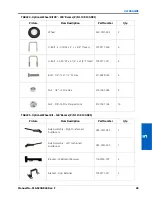
1. Locate the left and right ultrasonic sensors (P/N 063-0130-012 and 063-0130-014) in the AutoBoom installation
kit.
2. Remove the sensor from the existing plastic arm.
3. Install the sensors on the 12” S-type sensor arms (P/N 063-0131-592) using the supplied 5/16”-18 x 1-1/4” bolts
(P/N 311-0052-106), 5/16”-18 nylon insert lock nuts (P/N 312-4000-059) and 5/16” zinc flat washers (P/N 313-
2300-012).
4. Secure the left sensor (P/N 063-0130-014) to the front of the left boom using two 1-9/16” W x 2-1/2” L x 3/8”
thread U-bolts (P/N 107-0171-611) and four 3/8”-16 zinc flanged lock nuts (P/N 312-1001-164).
5. Tighten the nuts to ensure the sensor is mounted securely.
6. Repeat the steps above to mount the remaining boom sensor(s).
MOUNT THE CENTER RACK SENSOR
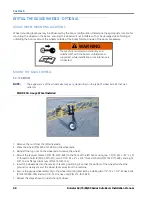
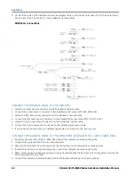
FIGURE 9. Center Rack Sensor
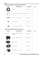
1. Mount the center sensor (P/N 063-0130-018) to the machine’s center rack using two 1-9/16” W x 2-1/2” L x 3/8”
thread U-bolts (P/N 107-0171-611) and four 3/8”-16 zinc flanged lock nuts (P/N 312-1001-164).
2. Tighten the nuts to ensure the sensor is mounted securely.
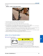
CONNECT THE SENSOR CABLES
1. Connect the left sensor cable (P/N 115-0171-527) to the connector on the outer left sensor.
2. Route the left sensor cable toward the AutoBoom valve.
3. Loop and tie-off any excess cable, allowing enough cable for boom folding and extension.
4. Repeat the steps above to connect the remaining sensor cables.
NOTE:
The sensor cables will be connected to the AutoBoom system in the wiring phase of installation.
Содержание RoGator 64 Series
Страница 9: ...2 Manual No 016 0230 044 Rev F 5 INTRODUCTION ...
Страница 10: ...CHAPTER 2 6 RoGator 64 74 86 SS Series AutoBoom Installation Manual ...
Страница 21: ...3 Manual No 016 0230 044 Rev F 17 POWERGLIDE POWERGLIDE HYDRAULIC SCHEMATIC ...
Страница 40: ...CHAPTER 4 36 RoGator 64 74 86 SS Series AutoBoom Installation Manual POWERGLIDE PLUS HYDRAULIC SCHEMATIC ...
Страница 47: ...Manual No 016 0230 044 Rev F 43 POWERGLIDE PLUS POWERGLIDE PLUS WIRING SCHEMATIC GEN I CABLING ...
Страница 48: ...CHAPTER 4 44 RoGator 64 74 86 SS Series AutoBoom Installation Manual GEN II CABLING ...
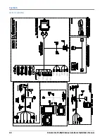
Страница 61: ...5 Manual No 016 0230 044 Rev F 57 ULTRAGLIDE ULTRAGLIDE HYDRAULIC SCHEMATIC ...
Страница 71: ...Manual No 016 0230 044 Rev F 67 ULTRAGLIDE ULTRAGLIDE WIRING SCHEMATIC GEN I CABLING ...
Страница 72: ...CHAPTER 5 68 RoGator 64 74 86 SS Series AutoBoom Installation Manual GEN II CABLING ...
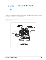
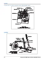
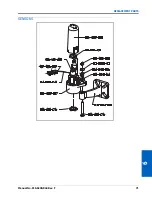
Страница 75: ...6 Manual No 016 0230 044 Rev F 71 REPLACEMENT PARTS SENSORS ...
Страница 76: ...CHAPTER 6 72 RoGator 64 74 86 SS Series AutoBoom Installation Manual ...

