5
Manual No. 016-0230-044 Rev. F
53
ULTRAGLIDE
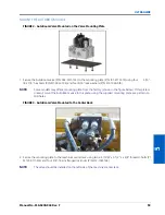
MOUNT THE AUTOBOOM VALVE
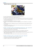
FIGURE 2. AutoBoom Valve Mounted on the Valve Mounting Plate
1. Secure the AutoBoom valve (P/N 063-0131-124) to the mounting plate (P/N 107-0171-619) using four 5/16”-
18 x 7/8” hex bolts (P/N 311-0052-104) and four 5/16” lock washers (P/N 313-1000-019).
NOTE:
Some models may offer a mounting plate from the factory (shown in the figure below). If this plate is
present, mount the AutoBoom valve to this plate, using the supplied mounting plate as a pattern to
drill holes.
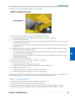
FIGURE 3. AutoBoom Valve Mounted to the Center Rack
2. Secure the mounting plate to the machine’s center rack using two 2-9/16” W x 3-1/2” L x 3/8” thread U-bolts (P/
N 107-0171-616) and four 3/8”-16 zinc flanged lock nuts (P/N 312-1001-164).
NOTE:
The valve should be installed on the left side of the machine’s center rack.
Содержание RoGator 64 Series
Страница 9: ...2 Manual No 016 0230 044 Rev F 5 INTRODUCTION ...
Страница 10: ...CHAPTER 2 6 RoGator 64 74 86 SS Series AutoBoom Installation Manual ...
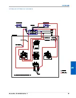
Страница 21: ...3 Manual No 016 0230 044 Rev F 17 POWERGLIDE POWERGLIDE HYDRAULIC SCHEMATIC ...
Страница 40: ...CHAPTER 4 36 RoGator 64 74 86 SS Series AutoBoom Installation Manual POWERGLIDE PLUS HYDRAULIC SCHEMATIC ...
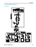
Страница 47: ...Manual No 016 0230 044 Rev F 43 POWERGLIDE PLUS POWERGLIDE PLUS WIRING SCHEMATIC GEN I CABLING ...
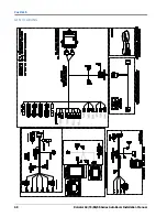
Страница 48: ...CHAPTER 4 44 RoGator 64 74 86 SS Series AutoBoom Installation Manual GEN II CABLING ...
Страница 61: ...5 Manual No 016 0230 044 Rev F 57 ULTRAGLIDE ULTRAGLIDE HYDRAULIC SCHEMATIC ...
Страница 71: ...Manual No 016 0230 044 Rev F 67 ULTRAGLIDE ULTRAGLIDE WIRING SCHEMATIC GEN I CABLING ...
Страница 72: ...CHAPTER 5 68 RoGator 64 74 86 SS Series AutoBoom Installation Manual GEN II CABLING ...
Страница 75: ...6 Manual No 016 0230 044 Rev F 71 REPLACEMENT PARTS SENSORS ...
Страница 76: ...CHAPTER 6 72 RoGator 64 74 86 SS Series AutoBoom Installation Manual ...


