4
Manual No. 016-0230-044 Rev. F
41
POWERGLIDE PLUS
CONNECT THE CAN/POWER CABLES - GEN I CABLES
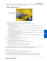
FIGURE 17. Existing CAN Terminator
1. Locate the CAN cable under the cat-walk on the right side of the machine.
• If a CAN passive terminator is on the CAN connector as shown in Figure 17 on page 41:
a. Remove the CAN terminator.
b. Connect the male CAN connection on the power cable (P/N 115-0230-007) to the connector from which
the terminator was removed.
c. Install the terminator on the CAN connection of the harness cable (P/N 115-0230-045) coming from the
AutoBoom node.
• If the CAN connector does not have a CAN passive terminator and another CAN cable is already connected:
a. Disconnect the existing CAN termination.
b. Connect the CAN connection from the power cable (P/N 115-0230-007) into the connector from which
the other CAN cable was unplugged.
c. Reroute the disconnected CAN cable to the CAN connection near the AutoBoom node on the harness
cable (P/N 115-0230-045).
d. Loop and tie-off any excess cable.
2. Locate the CAN power connector as shown in Figure 17 on page 41.
• If the CAN power connector is not is use:
a. Remove the dust cap from the power connection.
b. Insert the power connection into the controller cable (P/N 115-0230-007).
• If the CAN power connector is in use:
a. Locate the orange wire on the power cable (P/N 115-0230-007).
b. Route and connect the orange wire to a source switched power.
Recommended locations are on the Raven controller or in the machine’s cab. Several Raven consoles offer a +12V
switched power connector on the console cable, which may be used to switch the circuit.
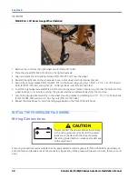
CONNECT THE POWER LEADS
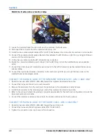
1. Locate the power cable that has the power and ground leads at one end.
2. Disconnect the machine’s connectors from the battery terminals.
3. Install the power lead on the positive battery terminal and reinstall the machine’s battery connector.
4. Install the ground lead on the negative battery terminal and reinstall the machine’s battery connector.
CAN Termination
Содержание RoGator 64 Series
Страница 9: ...2 Manual No 016 0230 044 Rev F 5 INTRODUCTION ...
Страница 10: ...CHAPTER 2 6 RoGator 64 74 86 SS Series AutoBoom Installation Manual ...
Страница 21: ...3 Manual No 016 0230 044 Rev F 17 POWERGLIDE POWERGLIDE HYDRAULIC SCHEMATIC ...
Страница 40: ...CHAPTER 4 36 RoGator 64 74 86 SS Series AutoBoom Installation Manual POWERGLIDE PLUS HYDRAULIC SCHEMATIC ...
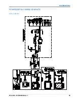
Страница 47: ...Manual No 016 0230 044 Rev F 43 POWERGLIDE PLUS POWERGLIDE PLUS WIRING SCHEMATIC GEN I CABLING ...
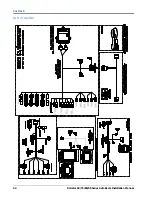
Страница 48: ...CHAPTER 4 44 RoGator 64 74 86 SS Series AutoBoom Installation Manual GEN II CABLING ...
Страница 61: ...5 Manual No 016 0230 044 Rev F 57 ULTRAGLIDE ULTRAGLIDE HYDRAULIC SCHEMATIC ...
Страница 71: ...Manual No 016 0230 044 Rev F 67 ULTRAGLIDE ULTRAGLIDE WIRING SCHEMATIC GEN I CABLING ...
Страница 72: ...CHAPTER 5 68 RoGator 64 74 86 SS Series AutoBoom Installation Manual GEN II CABLING ...
Страница 75: ...6 Manual No 016 0230 044 Rev F 71 REPLACEMENT PARTS SENSORS ...
Страница 76: ...CHAPTER 6 72 RoGator 64 74 86 SS Series AutoBoom Installation Manual ...

