5
P/N 016-0171-493 Rev. I
45
Startup, Initial Setup, and Setup Wizards
Using the Product Control Setup Wizard
1.
Touch the Product Control Setup Wizard icon to begin the setup wizard. The Speed Cal screen will display.
2.
Use the radio buttons toward the left side of the screen to select the type of speed sensor which will be
used with the control system.
3.
Touch the button labeled ‘Speed Cal’ and use the on-screen keypad to enter the calibration value for the
speed sensor installed on the vehicle. Refer to the
section on page 101 for more information about
the speed cal value.
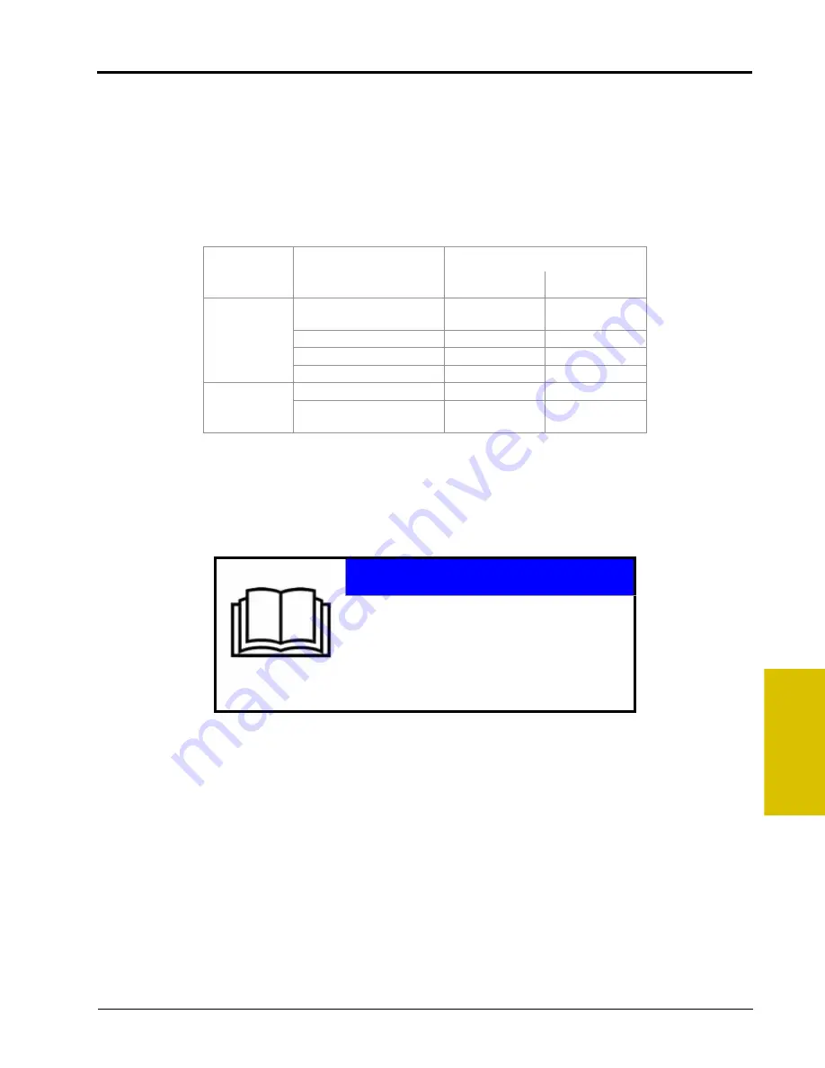
Raven Industries recommends the following speed calibration values for initial system setup.
These values are good starting points and generally yield adequate results, however, the speed cal should
be refined for each specific vehicle and speed sense system. See Appendix A,
, for instructions on refining the speed cal value.
Note:
The GPS speed over CANbus feature is only available with specific Raven speed sense nodes.
This feature utilizes NMEA speed over ground data transmitted over the CAN network which
eliminates the need for a separate, external speed sensor.
The test speed and distance values are not required to complete initial setup of the field computer.
Refer to the System Menu section on page 93 for detailed information about these settings.
Sensor Type
Setting
Used with
Recommended Initial Speed Cal
English
Metric
Radar/GPS
External Raven GPS
Receiver
785
199
Internal DGPS Receiver
812
206
GPS Speed over CANbus
1000
1000
Raven Radar
598
152
Wheel
Wheel Magnets
1000
254
Speedometer Drive Speed
Sensor
612
155
NOTICE
When using the GPS speed over CANbus
feature, no calibration or adjustment is
necessary or recommended to the speed cal
value. Losing GPS signal for more than a
second will also result in loss of the CAN speed
signal which may affect product application in
progress.
Содержание Envizio Pro
Страница 3: ......
Страница 13: ...Table of Contents x Envizio Pro and Envizio Pro II Installation and Operation Manual ...
Страница 32: ...3 P N 016 0171 493 Rev I 17 Installation FIGURE 1 Envizio Pro Kit Contents Drawing Number 054 2040 004 ...
Страница 51: ...Chapter 4 36 Envizio Pro and Envizio Pro II Installation and Operation Manual ...
Страница 65: ...Chapter 5 50 Envizio Pro and Envizio Pro II Installation and Operation Manual ...
Страница 193: ...Chapter 9 178 Envizio Pro and Envizio Pro II Installation and Operation Manual ...
Страница 197: ...Chapter 10 182 Envizio Pro and Envizio Pro II Installation and Operation Manual ...
Страница 229: ...Appendix D 214 Envizio Pro and Envizio Pro II Installation and Operation Manual ...
Страница 285: ...Index 270 Envizio Pro and Envizio Pro II Installation and Operation Manual ...


