Instructions for Use MPR1 DATALOGGER
Manufacturer:
RAUMEDIC AG, Hermann-Staudinger-Strasse 2, 95233 Helmbrechts, Germany
Page 17 of 98
3 Patient monitoring
Note: This chapter describes the units and their functions as well as the extension options of the MPR1.
A detailed description of the operation of the MPR1 is rendered in chapter 4
MPR1, and the technical data are listed in chapter 11
Technical parameters (Specification).
3.1 ECG
This feature is only available in devices up to the 2011 production year. (see 2.1
Applied part
type CF
Type:
single-channel ECG without monitoring
Number:
1
Where:
Fig. 2: Connection field, connection [18]
Application:
see below
Application: The ECG is used to assess the patient’s activity (heart rate). In neuro-surgery, the ECG triggers
the allocation of the pulse amplitudes of the ICP pulse wave (start of P1), measuring the ICP at the same
time.
The ICP pulse wave resembles a venous wave and has five small peaks (P1 – P5) whereby P1 to P3 are
arterially induced and P4 to P5 venously. Normally the amplitude amounts to 3 to 4 mmHg. In case of space
taken (by SAB or tumours for example) the pulse amplitudes increase caused by the vasodilatation, and
P1 drops below P2. If the pCO2 increases, the pulse amplitude increases as well. In case of an active
hydrocephalus, the pulse amplitude may increase in a sinusoidal peak-free form up to 40 mmHg.
The pulse wave analysis is an indirect compliance parameter (dimension for the intra-cranial reserve space)
because the pulse amplitude rises with decreasing compliance continuously linear with the ICP.
The ECG channel is type CF and has been classified as protected against defibrillation. The ECG channel
of MPR1 can be used for simple bipolar lead (preferably according to Eindhoven II) with display of the heart
rate.
Use only those ECG accessories which have
been listed in the overview of accessories. It is
only with these accessories that a protection
against the effects of a defibrillation is ensured.
Note: The ECG channel has not been provided
with a monitoring function.
Caution! The MPR1 has not been approved for
direct use on the heart.
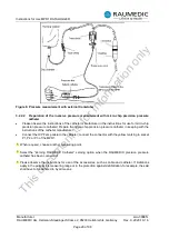
Figure 5: Applying the electrodes
An overmodulation of the input amplifier is not indicated. Thus, there is no indication of any distorted or
overdriven signal curves.
For the recommended position of the electrodes, please refer to Fig. 5. In this way the thorax is kept free
for a potentially required reanimation. Connect the patient cable with the electrodes and the ECG
connection socket
ECG
[18]. In the process, please observe that the coding bridges of the connector
correctly fit into the grooves of the socket. Please also check the correct seat of all plug-in connections of
the patient cable.
The display of the MPR1 renders the heart rate
HR
on the overview screen in the ECG window (buttom
right-hand side). Please observe that the display of the first value will take a few seconds on account of the
automatic amplification control.
By pressing the screen selector button , the graphics screen can be changed. The display will show the
ECG curve, and if additional sensors have been fitted, the display will be split into the corresponding number
This
document
is
for
information
only


