background image

Instructions for Use MPR1 DATALOGGER 


Manufacturer:  


zwo-399EN 

RAUMEDIC AG, Hermann-Staudinger-Strasse 2, 95233 Helmbrechts, Germany  

Rev. 9, 2020-10-16 


Page 73 of 98 

5  Power supply 
5.1  Mains power supply 


If the MPR1 is to be operated on mains power, mains adapter, which belongs to the scope of delivery, 

shall be used only (RAUMEDIC Art. No. 284007-002 or 284027-001, corresponding with the type plate). 


The mains adapter is not protected against moisture, and thus it must not get into contact with liquids. 


Please keep in mind that the mains adaptor may be connected only to correctly installed and approved 

sockets. 


5.2  Displays when operating on mains power 

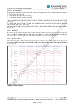
The Power On LED    [6] is lit when the apparatus is supplied by the external mains adapter.  If the 

apparatus has been switched on, this display is permanently lit; in addition the display illumination is 

switched on permanently, which cannot be switched off with the   key. The 

 symbol in the upper 

line of the display renders information on the charge condition of the battery: A full bar indicates a charged 

battery pack. If the apparatus has been switched off, but the unit is connected to the mains adapter, the 

display flashes and signals the charge of the battery. 


5.3  Battery operation 

The MPR1 has been equipped with a gas-tight and rechargeable battery. In fully charged condition, it can 

provide the MPR1 with power for approx. 12 hours (all channels active, display illumination off). The data 

of the operating period applies for a new and fully charged battery.  The frequent use of the display 

illumination reduces the operating period due to a larger demand of power. An aged battery caused by 

many charging and discharging cycles, for example, reduces the maximum operating period to be achieved 

as a matter of principle. The battery is charged in the MPR1 as soon as it has been connected to the 

external mains adapter. The battery is protected against overcharging. The MPR1 has been equipped with 

a deep-discharging protection system. Approximately half an hour before the apparatus is switched off 

automatically, an acoustic alarm is sounded. 

If the apparatus is not switched off at the end of the remaining operating time or if no mains adapter is 

connected, the apparatus is switched off at the end of the remaining operating time.  In this case, a 

continuous sound will be released for at least 30 seconds (typically one hour). As soon as the mains adapter 

is connected this warning sound will go off. If no mains operation is possible, switch on the apparatus and 

off again after a few seconds. Avoid a longer period of storage in discharged condition. 


  Please observe the information on the influence of storage as well as the recommendations on 

battery maintenance as otherwise the remaining operating period cannot be guaranteed.


5.4  Displays when operating on battery 

The Power On LED   [6] flashes when the apparatus is supplied by the internal battery. If the apparatus 

has been switched on, this display flashes permanently; the display illumination is switched off, but can be 

switched on again by pressing the   key. The display illumination is switched off automatically after 60 

seconds. The 

 symbol in the upper line of the display renders information on the charge condition 

of the battery: A full bar indicates a charged battery pack. If the apparatus has been switched off and is not 

connected up to the mains adapter, all displays are off. 


5.5  Influence of the storage conditions on the battery operation 

When the MPR1 is stored, the battery pack is subject to self-discharge, which is compensated by the 

software as far as possible. In order to guarantee the residual operating period in battery pack operation, 

the battery pack has to be charged completely after storage. Depending on the storage temperature, the 

condition prior to storage and the ambient temperature, complete charging will take between five and twenty 

hours. Avoid high storage and charging temperatures in order to counter excessive aging of the battery 

pack. Ideal conditions may be expected after complete battery maintenance. 


This 

document 

is 

for 

information 

only

Содержание MPR1

Страница 1: ...C AG Hermann Staudinger Strasse 2 95233 Helmbrechts Germany Rev 9 2020 10 16 Page 1 of 98 Instructions for Use MPR1 DATALOGGER REF 094474 001 and 094474 002 Firmware versions 2 10 0070 and 2 10 0070 H...

Страница 2: ...1 16 2 9 Catheter location and signal designations 16 3 Patient monitoring 17 3 1 ECG 17 3 2 Cabled invasive pressure measurement 18 3 2 1 General aspects 18 3 2 2 Preparation of the invasive pressure...

Страница 3: ...and deactivating the temperature alarms 51 4 4 4 2 Temperature graphics 51 4 4 4 3 Temperature trend 52 4 4 5 Telemetric pressure measurement 52 4 4 5 1 Making ICPT settings 55 4 4 5 2 Changing ICPT a...

Страница 4: ...Cleaning and maintenance 82 7 1 Cleaning the MPR1 82 7 2 Cleaning disinfecting and sterilising the cables and sensors 82 7 2 1 Cleaning 82 7 2 2 Disinfection 82 7 2 3 Sterilisation 83 7 3 Cleaning th...

Страница 5: ...all be considered part of the appliance and shall have to be kept available in the vicinity of the appliance The exact observation of the instructions for use shall be the pre requisite for the intend...

Страница 6: ...gnal output configures a medical system and thus he she shall be responsible for the fact that this system meets the requirements of standard IEC 60601 1 1 Simultaneous operation with other apparatuse...

Страница 7: ...d for telemetric pressure measurement with a pressure measurement implant No liquids or fluids shall enter the apparatus If this should happen nonetheless first remove the mains adapter from the socke...

Страница 8: ...erature T 2 channels Invasive pressure measurement and temperature measurement are significant performance characteristics of the unit These parameters are determined by using RAUMEDIC catheters for s...

Страница 9: ...es that meet the requirements of IEC 60601 1 2 2007 for differentiation see Section 10 Electromagnetic compatibility are contraindicated for simultaneous use with electrosurgical devices The unit is n...

Страница 10: ...e left hand bank of keys and are marked with their functions The key functions are described in Table 1 2 5 2 Keys with context sensitive functions The unit has eight context sensitive defined functio...

Страница 11: ...he background lighting on off in battery operated mode toggle function After 60 seconds the lighting is switched off automatically During mains operation this key has no function 4 The bell symbol swi...

Страница 12: ...Combine analogue outputs 22 E RS232 interface cf 3 6 Interface for the extension of the apparatus 23 PC USB interface cf 3 7 PC interface 24 Power connection for mains adapter cf 4 1 General aspects 2...

Страница 13: ...for use must be read The triangular LED at the left hand top has the following significance Display for alarms Flashing yellow LED if alarm has average priority Flashing red LED if alarm has high prio...

Страница 14: ...007 002 respectively 284027 001 authorised by the manufacturer may be used Ext Bi directional digital input output The caution sign below socket Ext indicates that only accessory parts authorised by t...

Страница 15: ...ging label have the following significance Keep dry Keep away from sunlight Consult instruction for use Manufacturer Date of manufacture Please observe disposal instructions Do not put old units into...

Страница 16: ...e output 1 Out 2 connection socket for analogue output 2 PC connection socket for USB cable Power connection socket for mains adapter P1 connection socket for pressure sensor P1 P2 connection socket f...

Страница 17: ...he pulse amplitude rises with decreasing compliance continuously linear with the ICP The ECG channel is type CF and has been classified as protected against defibrillation The ECG channel of MPR1 can...

Страница 18: ...chemical processes on the ECG electrodes may have a negative effect on the ECG lead For this reason please only use the electrodes recommended in the list of accessories Do not use electrodes of diffe...

Страница 19: ...s its scale alarm source and alarm limits Specification of the pressure channels cf 11 Technical parameters Specification Recommended accessories cf 9 Accessories 3 2 2 Preparation of the invasive pre...

Страница 20: ...pressure catheter in keeping with the instructions of the catheter manufacturer Connect the ICP Temp cable to the catheter connect the connector with the yellow marking to socket P1 P2 or P3 of the M...

Страница 21: ...e subjected to extensive measurements Based on the evaluation of these measurement results the parameters of RAUMEDIC catheters are precisely set in the works the offset error is extremely low Based o...

Страница 22: ...nd when the Retention of zero value option is selected Use this option only if you are well aware of the function of this process Use this option only with the same pressure catheter 3 2 2 3 3 Convent...


Страница 23: ...surement location label ICPT The measurement location allocation of the pressure channel sets its scaling alarm source and alarm limits Patient risk is inherent in invasive procedures Use aseptic tech...

Страница 24: ...lemetry catheter Please note that telemetric data transfer requires exact alignment of the reader aerial with the telemetry catheter and that the bridgeable distance is limited 17 mm Reader aerial Tel...

Страница 25: ...aving to ensure an absolute accuracy of 0 01 Celsius 3 4 1 Preparing the temperature measurement As soon as the temperature sensor has been connected to one of the sockets 27 or 28 and is subjected to...

Страница 26: ...or of the pressure amplifier of the third party system When using the analogue output it is imperative that you proceed in keeping with chapter 4 6 1 Combine analogue outputs As from 17th March 2004 t...

Страница 27: ...ure 2 Connection field connection 23 Application connection of laptop Use approved accessories only By means of the USB cable RAUMEDIC article No 283949 001 this USB interface can be used to connect a...

Страница 28: ...pplied it has to be connected to the mains voltage Now connect the red connector of the mains adapter cable with the red socket of the MPR1 Please keep in mind that only one approved electrical applia...

Страница 29: ...has been switched on the start screen will always be displayed cf Figure 9 By repeated actuation of the screen forward key you skip between the individual screens 4 2 Start screen Alarm LED Delete Sel...

Страница 30: ...lease observe the other key function if the Shift key is pressed in addition 4 2 2 Deleting the memory Please observe The memory mode set has a decisive influence on the potential recording duration O...

Страница 31: ...atement on the display After the deletion the memory bar is completely black As you have deleted the existing data in this case you can no longer continue with the previous patient rather a new patien...

Страница 32: ...ction press the ESC key to return to the previous step From firmware version 2 00 0053 the option now exists of viewing the trend data of the last measurement 4 2 6 View last measurement The patient I...

Страница 33: ...on press OK To cancel your selection and return to the previous step press ESC Software version Once the memory mode is specified press OK to close the window You cannot close the window if any pulldo...

Страница 34: ...device memory function is not considering any subsequent data archiving or visualisation on the PC wishes to carry out measuring as quietly and smoothly as possible without unnecessary technical alarm...

Страница 35: ...he symbol Even in memory mode No storage trend display for up to 8 hours is possible Beyond this period older data are overwritten 4 2 6 View last measurement From firmware version 2 00 0053 the optio...

Страница 36: ...n monitoring mode 4 3 Alarm limit selection From here you carry out alarm limit selection By pressing the Act key the alarm limit settings of the last measurement are adopted for the current measureme...

Страница 37: ...data on the basic settings of the alarm limits the alarm activation and the settings of the alarm limits please refer to chapter 4 9 1 Physiological alarms Never use force Force will definitely cause...

Страница 38: ...ue socket ECG Once you have carried out a preliminary setting for the patient and the memory mode close the window by pressing OK and skip to the overview screen Please keep in mind that some seconds...

Страница 39: ...his setting is suitable for standard monitoring Please chose Maximum in case of several disturbed signals However please keep in mind that the signal morphology is distorted Use the arrow keys to sele...

Страница 40: ...rt rate trend In order to skip from the graphics screen to the trend screen press the key The navigation field renders available keys to set the temporal resolution as well as page up and page down ke...

Страница 41: ...essories Observe the permissible measuring range of the transducer The MPR1 has three pressure input sockets P1 P2 P3 to connect pressure sensors external transducers or micro chip precision pressure...

Страница 42: ...on In the next step the pressure sensor has to be zeroed For this purpose skip to the Zero calibration pull down menu Press the Menu key and selected the zeroing procedure recommended for the pressure...

Страница 43: ...e been activated Please make sure that you have not switched off the acoustic alarm permanently acoustic alarm permanently off The right hand column of the display holds the navigation field in which...

Страница 44: ...d ICP2 are observed If only one intra cranial pressure ICP1 or ICP2 is available the CPP is calculated from ART and ICP1 or ICP2 depending on which measuring location has been allocated Please note th...

Страница 45: ...not set the limiting values to extreme values which could render the alarm system useless 4 4 3 2 1 Changing the pressure limiting value Increasing the lower limiting value Keep the UG key pressed un...

Страница 46: ...e ICP ICP1 ICP2 ICPT to an external system via the analogue outputs The pressure signals can be any two pressures including the ICPT For more information see point 3 5 Analogue outputs You can activat...

Страница 47: ...ve been changed Set the external system alarm limits to maximum 350 mmHg if monitoring is required 4 4 3 4 Pressure graphics In order to skip to the graphics screen press the key Screen will be access...

Страница 48: ...verview of the entire trend fast without having to press the key several times subsequently you can set a higher resolution for the time range of your choice Six time ranges are available width of the...

Страница 49: ...ed accessories only The MPR1 has two temperature input sockets Temp 1 and Temp 2 to connect temperature sensors temperature sensors from Exacon or RAUMEDIC multi parameter catheter with integrated tem...

Страница 50: ...her settings T2 alarm limits 4 4 4 1 Changing the temperature settings The right hand column of the display holds the navigation field in which you can use the soft keys to carry out further adjustmen...

Страница 51: ...vate or deactivate an alarm please proceed as follows Press the key T1 or T2 if another temperature sensor has been connected Use the arrow keys to navigate into the table field the settings of which...

Страница 52: ...ution Coarser temporal resolution Rough backward navigation Fine backward navigation Fine forward navigation Rough forward navigation 4 4 5 Telemetric pressure measurement Observe section 3 3 Telemetr...

Страница 53: ...nt channel additional to the existing cabled pressure measurement channels P1 P2 P3 but rather instead of the catheter connected to P1 At the MPR1 the catheter which was previously plugged in to the M...

Страница 54: ...ranial pressure The resolution of the ICPT display is 1 mmHg without any decimal places As from firmware version 2 00 0063 respectively 2 00 0063 HW2 the ID of the telemetric catheter is displayed in...

Страница 55: ...fy the marked field 4 4 5 2 1 Changing ICPT thresholds Setting of the ICPT alarm limits as well as the alarm activation alarm deactivation takes place analogously to the ICP settings s 4 4 3 2 1 Chang...

Страница 56: ...ertain or individual parameters in a higher resolution amplitude In screen as well as in screen it is possible to deselect tracks in the graphics display after having pressed the Shift key of the conn...

Страница 57: ...tem Carry out a zero compensation of the pressure channel of the third party system MPR1 provides 0 mmHg Check the sensitivity of the third party system MPR1 provides 20 mmHg Select the pressure chann...

Страница 58: ...er to compensate the drift The zero point of the pressure sensor is not lost by this action If monitoring is to be carried out using the analogue outputs the upper alarm limit for the third party moni...

Страница 59: ...els Press Diag F key to access Device diagnostics T T Software version F key to start the test of the temperature channels F key to start the alarm system check F key to start the test of the ecg chan...

Страница 60: ...g changed to contrast press the Menu key Step 4 By pressing the or keys the contrast value set can be changed Press the ESC key to return to the previous step Step 5 Set a new contrast value press the...

Страница 61: ...that on saving the data on the PC two files are created one for the time prior to the time setting and one for the time after Thus the data cannot be viewed continuously On the MPR1 the trend data fro...

Страница 62: ...us step Complete your settings by pressing the OK key Step 4 The modified time is displayed Setting the date Step 1 Use the arrow keys to navigate in the date field Step 2 Press the Menu key to set th...

Страница 63: ...atively one of the three following set up settings can be chosen for the scaling In the device setup window press the Scal key The currently set scaling is displayed In this case Automatic has been se...

Страница 64: ...o the overview screen and press the Shift F5 key key symbol A pop up window will render information on the active key lock Button block active to unblock button press F5 and hold This note will disapp...

Страница 65: ...tes optical and acoustic alarms according to the alarm priority In order to make optical alarms more noticeable the background illumination of the display is switched on for every alarm even if the ap...

Страница 66: ...muting reset exists Muting reset is also possible with key lock activated However global muting reset is not possible with key lock activated Global suppression If this button alarm is pressed for tw...

Страница 67: ...g is transferred to the measuring signal of the pressure sensor and the amplitude is then evaluated Under the highly unlikely assumption that at the measuring location of ART with relatively high phys...

Страница 68: ...re ICP1 ICPA mmHg 0 20 nein 0 400 1 Pressure ICP2 ICP mmHg 0 30 ja 40 400 1 Pressure ICP2 ICPA mmHg 0 20 nein 0 400 1 Pressure ICP1 2 CPP mmHg 50 100 ja 0 400 1 Pressure D1 SYS mmHg 100 180 ja 40 400...

Страница 69: ...peration of the apparatus is no longer ensured or where this fact has to be expected respectively and into those alarms in which measuring or saving functions can no longer be carried out at all or to...

Страница 70: ...efect Remove the reader from the device and please contact technical services The implant software version is not compatible with the measurement system Use another pressure measurement implant or con...

Страница 71: ...s been acknowledged with Info OK OK Exceptions are provided by the sensor alarms 5 and 6 These sensor alarms remain even after pressing the info key 4 9 5 limitations No alarm is generated from the EC...

Страница 72: ...es approx 7 s break Table 7 Alarm conditions 1 See Table 1 in chapter 2 3 Contraindications 2 Individual actions are indicated by individual short sounds 3 Physiological and technical alarm 4 9 7 Veri...

Страница 73: ...charging protection system Approximately half an hour before the apparatus is switched off automatically an acoustic alarm is sounded If the apparatus is not switched off at the end of the remaining o...

Страница 74: ...that the charging current has to be reduced at an ambient temperature of over 35 Celsius and that the charging time thus increases If the operating period of the battery is too low after this process...

Страница 75: ...om a number of advantages these new functions of MPR1 also include some few fault possibilities the identification and removal of which shall be mentioned hereinafter Fault Potential cause Removal Rea...

Страница 76: ...not be guaranteed anymore The curve for this channel is still displayed but the values are no longer taken into consideration for the trend as they are unreliable By removing and re connecting the pre...

Страница 77: ...ngs Once you have switched the device off and on again you can continue working Check the settings e g date time alarm limits Please follow the instructions It is imperative that the settings of the a...

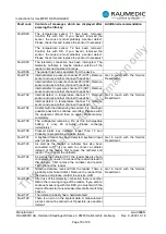
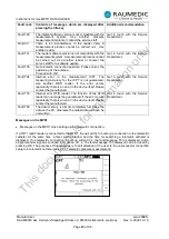
Страница 78: ...o message is available with recommendations for problem solution Fault code Contents of messages which are displayed after pressing the Info key Additional recommendation Fault P01 The measured pressu...

Страница 79: ...nother channel if needs be Fault T04 A defect with the data saving has arisen it is no longer possible possible to continue recording Please switch the equipment off and then on again Erase memory com...

Страница 80: ...the error occurs repeatedly there is an error in the device itself Please contact the manufacturer Get in touch with the Service Department Fault T35 Internal error RFID reader The function of the RF...

Страница 81: ...ection is displayed Datalog software has been started up Save data on PC has been selected download Press Start The following message is displayed on the MPR1 whilst downloading data The user can clos...

Страница 82: ...us or you are in doubt about the safety of the apparatus have the apparatus checked by a service workshop Subsequently a safety related check is necessary 7 2 Cleaning disinfecting and sterilising the...

Страница 83: ...ng a cleaned disinfected and sterilised cable check it for its technically functional safety In order to prevent accidental re use destroy disposable adhesive electrodes immediately after use 7 3 Clea...

Страница 84: ...uirement for safety check according to Medical Devices Operator Ordinance MPBetreibV 11 in conjunction with Annex 1 point 3 As the manufacturer we provide you with the option of having the necessary c...

Страница 85: ...3959 002 Table stand DATALOGGER 094858 001 Cable DATALOGGER GE MARQUETTE length 2 00 m 094868 001 Cable DATALOGGER Philips HP length 2 00 m 094878 001 Cable DATALOGGER Siemens Draeger Infinity length...

Страница 86: ...25 C 0 4 K 25 37 C 0 2 K 37 39 C 0 1 K 39 45 C 0 2 K The catheter is placed in the water and dimmed during the tests 10 1 2 General information Use of this equipment adjacent to or stacked with other...

Страница 87: ...2700 MHz 1 kHz AM 80 3 V m at 2 Hz Immunity to proximity fields from RF wireless communications equipment according IEC 61000 4 3 385 MHz Pulse modulation 18 Hz 27 V m 450 MHz FM 5Hz deviation 1 kHz s...

Страница 88: ...irements of IEC 60601 1 2 2007 Note Special precautions in respect of electromagnetic compatibility EMC must be taken for medical electrical devices and the devices must be installed and operated in c...

Страница 89: ...e patient lies below the minimum amplitude and or the values given in section 11 1 Technical data device use could lead to inaccurate results 10 3 Electromagnetic emissions The MPR1 is intended for us...

Страница 90: ...r conductor outer conductor 2 kV voltage outer conductor earth The quality of the supply voltage should correspond to that of a typical commercial or hospital environment Voltage drops short temporary...

Страница 91: ...an the conformity level at all frequencies as demonstrated by an on sitea investigation b Interference is possible in the area surrounding devices carrying the following symbol At 80 MHz and 800 MHz t...

Страница 92: ...ted power W Safe distance dependent on emitter frequency m 150 kHz to 80 MHz d 1 17 P1 2 80 MHz to 800 MHz d 1 17 P1 2 800 MHz to 2 5 GHz d 2 33 P1 2 0 01 0 12 0 12 0 24 0 1 0 37 0 37 0 74 1 1 17 1 17...

Страница 93: ...e sensor 15 25 Celsius 0 2 K plus 0 2 K of the sensor Scanning rate 1 Hz Defibrillation protection Yes Invasive pressure Number of channels 3 Designation of the measuring location ART CVP ICP1 ICP2 GP...

Страница 94: ...60 dB A 1 m in stand holder Display Black white LCD 320 x 240 pixel 1 4 VGA 74 x 97 mm Trend display optional 4 min 8 min 20 min 40 min 80 min or 4 h Alarm limits to be selected by menu Language Germ...

Страница 95: ...instruments for which the use of the 284027 001 mains adapter is specified the permissible range is 620 to 1050 hPa 12 Environment and disposal All components of the MPR1 inclusive of its packaging ha...

Страница 96: ...49 Information and warning symbols 13 Inspections 84 Intended use 8 Invasive pressure measurement settings 43 K Key lock 64 L Language version setting 60 LCD background illumination 65 M Maintenance...

Страница 97: ...ormity Group No 0034 Designation of the Conformity Group RAUMEDIC MPR 1 DATALOGGER Class IIb are developed produced tested and sold in accordance with the requirements of EC directive 93 42 EEC Append...

Страница 98: ...mity group no 0039 Name of the conformity group Transdermal telemetry system readP Class AIMD are developed produced tested and sold in accordance with the requirements of EC directive 90 385 EEC Appe...

Отзывы: