Instructions for Use MPR1 DATALOGGER
Manufacturer:
RAUMEDIC AG, Hermann-Staudinger-Strasse 2, 95233 Helmbrechts, Germany
Page 19 of 98
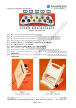
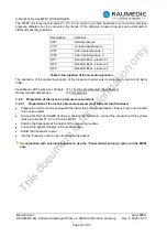
The MPR1 has three input sockets P1, P2, P3, to which up to three transducers or micro-chip precision
pressure catheters can be connected. By means of the software, pressure inputs can be allocated to
different measuring locations.
Designation
Definition
ART
arterial pressure
CVP
central venal pressure
ICP1
intra-cranial pressure 1
ICP2
intra-cranial pressure 2
GP1
standard label - pressure 1
GP2
standard label - pressure 2
GP3
standard label - pressure 2
Table 4: Designation of the measuring location
The allocation of the measuring location of the pressure channel sets its scale, alarm source and alarm
limits.
Specification of the pressure channels: cf. 11 Technical parameters (Specification)
Recommended accessories:
3.2.2 Preparation of the invasive pressure measurement
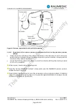
3.2.2.1 Preparation of the invasive pressure measurement with external transducer
•
Prepare the monitor set in keeping with the instructions of the manufacturer. Ensure that no air is locked
in the hose system.
•
Connect the DATALOGGER transducer cable to the transducer; connect the connector with the yellow
marking to socket P1, P2 or P3 of the MPR1.
•
Position the transducer at the height of the measuring location.
•
Connect the patient catheter to the pressure hose.
•
Adjust the transducer to zero.
•
Use the three-way cock to open the hose to the patient.
In conjunction with external transducers, use the “Conventional zeroing“ option on the MPR1
only.
This
document
is
for
information
only


