background image

UHA S

TANDARD 

U

NIT 

H

EATER 

I

NSTALLATION 

O

PERATION AND 

S

ERVICE 

M

ANUAL

2 of 59

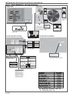
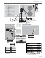
Figure 1: UHA[T][M][X][S]150 - 250 Label Placement

*For separated combustion units only.
**For modulating units only.

Description

Part Number

Logo Label

91031102

Cut Hazard Label

91010430

Vent Length Label

91039505

Vent to Outdoors Label

91010427

Warning Label

91010429

Rating Plate Label

91010418

Installation Label

91010431

Instruction Location Label

91010433

Lighting Instruction Label

91010425

Venting Arrangement Label*

91010426

Proposition 65 Label

91070015

0-10VDC Modulating Label**

91040196

Содержание UHAM 150

Страница 1: ... done by a contractor qualified in the installation and service of gas fired heating equipment or your gas supplier Improper installation adjustment alteration service or maintenance can result in death injury or property damage Read the Installation Operation and Service Manual thoroughly before installing or servicing this equipment Installer Please take the time to read and understand these ins...

Страница 2: ......

Страница 3: ... non respect de ces instructions peut entraîner la mort des blessures corporelles ou des dommages matériels ATTENTION L installation doit être effectuée par un installateur éprouvé contractant qualifié dans l installation et la maintenance du système de chauffage par infrarouge activé au gaz L installation l ajustement l altération le démarrage ou l entretien inadéquat peuvent causer la mort des b...

Страница 4: ......

Страница 5: ...S Series Internal Wiring Diagram for Single Stage Gas Valves 22 10 4 UHA X S Series Ladder Wiring Diagram for Single Stage Gas Valves 23 10 5 UHA T X S Series Internal Wiring Diagram for Two Stage Gas Valves 24 10 6 UHA T X S Series Ladder Wiring Diagram for Two Stage Gas Valves 25 10 7 UHA M X S Series Internal Wiring Diagram for Modulating Gas Valves 26 10 8 UHA M X S Series Ladder Diagram for M...

Страница 6: ...16 4 Dimension Data for Models UHA T M X S 300 400 57 16 5 General Technical Data Table 58 16 6 Technical Data Table 58 SECTION 17 The RAPID UHA Series Warranty 59 ...

Страница 7: ...ertical and Horizontal Vent Termination Separated Combustion Heater 16 Figure 11 Gas Connection 19 Figure 12 Automatic Burner Control Sequence 30 Figure 13 Single Stage Gas Valve for Models UHA X S 150 400 31 Figure 14 Two Stage Gas Valve for Models UHA T X S 150 400 31 Figure 15 Modulating Gas Valve for Models UHA M X S 150 400 32 Figure 16 LED Diagnostic Codes 36 There are references in this man...

Страница 8: ......

Страница 9: ... and operated under the general concepts of reasonable use and installed using the best building practices This equipment is not intended for use by persons including children with reduced physical sensory or mental capabilities or lack of experience and knowledge unless they have been given supervision or instruction concerning use of the equipment by a person responsible for their safety Childre...

Страница 10: ...ly Description Part Number Logo Label 91031102 Cut Hazard Label 91010430 Vent Length Label 91039505 Vent to Outdoors Label 91010427 Warning Label 91010429 Rating Plate Label 91010418 Installation Label 91010431 Instruction Location Label 91010433 Lighting Instruction Label 91010425 Venting Arrangement Label 91010426 Proposition 65 Label 91070015 0 10VDC Modulating Label 91040196 ...

Страница 11: ...mber Logo Label 91031102 Cut Hazard Label 91010430 Vent Length Label 91039505 Vent to Outdoors Label 91010427 Warning Label 91010429 Rating Plate Label 91010418 Installation Label 91010431 Instruction Location Label 91010433 Lighting Instruction Label 91010425 Venting Arrangement Label 91010426 Proposition 65 Label 91070015 0 10VDC Modulating Label 91040196 ...

Страница 12: ...0033 is illustrated on the back cover Know your model number and installed configuration Model number and installed configuration are found on the heater serial plate and throughout the Installation Operation and Service Manual 2 2 Corrosive Chemicals Rapid Engineering LLC cannot be responsible for ensuring that all appropriate safety measures are undertaken prior to installation this is entirely ...

Страница 13: ...ndoors Must be installed in a level position with horizontal discharge May be mounted on a shelf of non combustible material May be suspended from above See Page 9 Figure or from wall brackets of sufficient strength to support the heater as listed in the Technical Data Table on Page 56 Section 16 2 and Page 58 Section 16 5 Drop rods must be a minimum of 3 8 diameter mild steel Four suspension poin...

Страница 14: ...cinity of this heater The stated clearances to combustibles represents a surface temperature of 90 F 50 C above room temperature Building materials with a low heat tolerance such as plastics vinyl siding canvas tri ply etc may be subject to degradation at lower temperatures It is the installer s and owner s responsibility to assure that adjacent materials are protected from degradation Maintain cl...

Страница 15: ...ers may be mounted at a higher level if destratification fans are installed For Models UHA 150 400 venting directly from top of heater is not applicable For roof terminal vent elbow duct off back of heater is required Clearance to Vent 2 5 cm 31 79 cm minimum is necessary for servicing The heater must always be installed at least 6 1 8 m above the floor The vent pipe must have clearance from combu...

Страница 16: ...vision Canada Refer to Natural Gas and Propane Installation Code Standard CSA B149 1 latest revision 5 4 Electrical The heater must be electrically grounded in accordance with the following codes United States Refer to National Electrical Code NFPA 70 latest revision Wiring must conform to the most current National Electrical Code local ordinances and any special diagrams furnished Canada Refer to...

Страница 17: ...y lines must not be used to support the heater Do not locate the gas or electrical supply lines directly over the path of the flue products from the heater The heater must be installed in a location that is readily accessible for servicing The heater must be installed in accordance with clearances to combustibles as indicated on the wall tag and in this manual 6 2 Suspension For typical suspension...

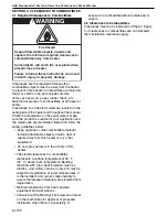
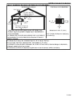
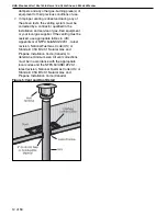
Страница 18: ...or that can be opened in any building any non mechanical air supply inlet to any building or of the combustion air inlet of any other piece of equipment 7 2 Vent Installation Maintain clearances to combustibles at all times for safety Clearances are the required distances that combustible objects must be away from the heater to prevent serious fire hazard See Page 7 Figure 3 For vented units the v...

Страница 19: ...sed at the roof or wall penetration instead of a thimble Ensure vent manufacturer s clearance from vent material is maintained Seal annular space of the type B 1 vent as well as all joints in the remaining vent 7 7 Replacing an Existing Heater in a Venting System When replacing an existing heater in a venting system the venting system may not be properly sized to vent the new heater The following ...

Страница 20: ... gas fired equipment or your local gas supplier If the venting must be resized use appropriate tables in US Appendix G of NFPA 54 ANSI Z223 1 latest revision National Fuel Gas Code US or Standard CSA B149 1 Natural Gas and Propane Installation Code Canada to determine minimum size All vent corrections must be in accordance with the appropriate local codes and the NFPA 54 ANSI Z223 1 latest revisio...

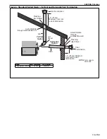
Страница 21: ...cal Option Horizontal Option Vent 90 Bend 12 31 cm Minimum from roof to vent termination Vent Termination Listed thimble through combustible wall Flashing By Others 12 31 cm Minimum from wall to vent termination Listed thimble through combustible roof NOTE Vent supports not shown Model Vent Diameter Part Number UHA T M X 150 400 4 10 cm 90502102 ...

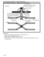
Страница 22: ...positioned to avoid direct opposition between streams of combustion gases Roof 2 6 m Minimum Type B vent cap 7 18 cm or 8 20 cm may be used These are not available from the manufacurer Roof Flashing Approved Thimble If Applicable Type B Vent Pipe 4 10 cm Single Wall Pipe 4 10 cm Single Wall Pipe D Area must equal sum of open area of individual vents D Single Wall Pipe The last section of vent pipe...

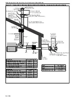
Страница 23: ...00 400 5 13 cm 90502105 4 10 cm Single Wall Vent Pipe By Others Seal joint between single wall and Type B vent with silicone sealant Use 3 sheetmetal screws equally spaced around joint Use 3 sheetmetal screws equally spaced around collar Concentric Vent Box 6 15 cm or 8 20 cm Single Wall Inlet Air Pipe By Others One piece of 4 10 cm diameter 1 4 6 cm airspace type B vent Selkirk Model RV or equiva...

Страница 24: ...rm Collar By Others Attach with 3 sheet metal screws 12 31 cm Minimum from roof to combustion air terminal Flashing By Others 12 31 cm Minimum from wall to combustion air terminal Description Part Number Qty Concentric Vent Kit 150 250 UHVK1 Concentric Vent Box Top Side Assembly 90504113 1 Concentric Vent Box Bottom Assembly 90504112 1 Screw 6 x 3 8 Self Drilling 91119100 14 4 Vent Terminal with B...

Страница 25: ...ide Combustion Air Supply If outside combustion air supply is required separated combustion model UHA T M X S heaters must be used Caution If the building has a slight negative pressure or corrosive contaminants such as halogenated hydrocarbons are present in the air an outside combustion air supply to the heater is required Seal all combustion air pipe joints The outside air terminal must not be ...

Страница 26: ... included in the layout drawing contact the local gas supplier An isolating valve and union connection should be used and fitted into the supply adjacent to the heater A minimum 1 8 NPT plugged tapping accessible for test connection must be installed immediately upstream of the gas supply connection to the heater For suspended heaters an approved metal flexible connection between the isolating val...

Страница 27: ... Heavy Gauge Pipe Gas Connector Option A Stainless Steel Flexible Gas Connector Do not twist flexible gas connector Ensure all joints are gas tight CAUTION Hold gas nipple securely with pipe wrench when attaching flexible gas connector Failure to follow these instructions can result in product damage Product Damage Hazard ...

Страница 28: ...om thermostat should be mounted on a vibration free wall or column at a height of approximately 5 1 5 m from the floor to measure the ambient temperature It should be clear of both cold drafts and the direct path of warm air from the heater Avoid mounting thermostat on outside walls or in areas directly exposed to radiant heat or sunlight Install wall tag in a visible location near thermostat See ...

Страница 29: ...SECTION 10 WIRING 21 of 59 10 2 Low Voltage Thermostat for Models UHA T M X S 150 400 NOTE Models 300 400 have two axial fans NOTE Electrical supply is located below terminal strip ...

Страница 30: ...iagram for Single Stage Gas Valves NOTE For field wiring into service junction box or if any of the original wire supplied with the heater must be replaced it must be replaced with wiring material having a temperature rating of at least 221 F 105 C and 600 volts For supply connections use No 14 AWG or larger wires ...

Страница 31: ...s Valves NOTE For field wiring into service junction box or if any of the original wire supplied with the heater must be replaced it must be replaced with wiring material having a temperature rating of at least 221 F 105 C and 600 volts For supply connections use No 14 AWG or larger wires ...

Страница 32: ...age Gas Valves 1 W2 HIGH LOW CONTROL HIGH LOW COMMON NOTE For field wiring into service junction box or if any of the original wire supplied with the heater must be replaced it must be replaced with wiring material having a temperature rating of at least 221 F 105 C and 600 volts For supply connections use No 14 AWG or larger wires ...

Страница 33: ...es HIGH STAGE NOTE For field wiring into service junction box or if any of the original wire supplied with the heater must be replaced it must be replaced with wiring material having a temperature rating of at least 221 F 105 C and 600 volts For supply connections use No 14 AWG or larger wires ...

Страница 34: ... Diagram for Modulating Gas Valves NOTE For field wiring into service junction box or if any of the original wire supplied with the heater must be replaced it must be replaced with wiring material having a temperature rating of at least 221 F 105 C and 600 volts For supply connections use No 14 AWG or larger wires ...

Страница 35: ...alves NOTE For field wiring into service junction box or if any of the original wire supplied with the heater must be replaced it must be replaced with wiring material having a temperature rating of at least 221 F 105 C and 600 volts For supply connections use No 14 AWG or larger wires ...

Страница 36: ...ALLATION OPERATION AND SERVICE MANUAL 28 of 59 10 9 Electrical Connection to the Heater Note Junction box is not provided with heater Conduit can also be attached directly to heater with wire junction made within the heater cabinet ...

Страница 37: ...e gas installation including the gas meter must be inspected tested for gas tightness and purged in accordance with local and national codes Ensure that the air is fully purged from the heater inlet pipe up to the main gas valve inlet test nipple 11 1 4 Mechanical Checks 1 Check that the fan s are free to run and delivery louvers are turned to give required air deflection 2 Check that the flue and...

Страница 38: ...gure 12 There will be no ignition of the burner and lockout will occur which proves the controls are operating correctly Figure 12 Automatic Burner Control Sequence Burner Sequence for Ignition Control Flame Signal Start Gas Valve Ignition Spark Thermostat 24 V SHUT DOWN RUN START ts 10 Seconds Signals Output By Control Required Incoming Signals Flue Blower Pressure Switch P C NO NC 30 Seconds Pur...

Страница 39: ... Inlet I l t P TOP VIEW END VIEW Description Part Number Gas Valve 150 250 NG 90032505 Gas Valve 150 250 LP 90032506 Gas Valve 300 400 NG 90032520 Gas Valve 300 400 LP 90032521 PSI IN C ON OFF LO HI Regulator Outlet Pressure Gas Inlet Inlet Pressure TOP VIEW END VIEW Description Part Number Gas Valve 150 250 NG 90032530 Gas Valve 150 250 LP 90032531 Gas Valve 300 400 NG 90032532 Gas Valve 300 400 ...

Страница 40: ...of 59 Figure 15 Modulating Gas Valve for Models UHA M X S 150 400 Description Part Number Gas Valve 150 250 NG 90032505 Gas Valve 150 250 LP 90032506 Gas Valve 300 400 NG 90032520 Gas Valve 300 400 LP 90032521 1 2 Exa Valve 150 250 90032550 3 4 Exa Valve 300 400 90032551 ...

Страница 41: ...ive To adjust high fire burner pressure remove regulator cover from Honeywell single stage gas valve and turn regulator adjustment screw to set required burner pressure as stated in the Technical Data Table for the correct gas and model on Page 56 Section 16 3 and Page 58 Section 16 6 3 To measure low fire burner pressure disconnect 10 VDC signal to modulating valve NOTE Low fire burner pressure i...

Страница 42: ...eater for service or during off season 11 5 External Controls External controls may include time switch interlock switch room thermostat and frost thermostat Operate each control to ensure that they function correctly Set the switches if fitted and thermostat s to the users requirements 11 6 Complete the Start Up Ensure that all covers are fitted correctly and all test points are properly sealed 1...

Страница 43: ...tely The fan will continue to run for 90 seconds To restart turn the thermostat on or above room temperature 12 3 Simple Troubleshooting Some possible reasons for the heater not operating are 1 Gas supply not ON 2 Electricity supply not ON 3 The time and or temperature controls are not ON 4 A limit switch may have operated This may be caused by an interruption of the electrical supply failure of t...

Страница 44: ...FAULT MODE Slow Flash Normal Operation No call for heat Fast Flash Normal Operation Call for heat 2 Flashes Ignition Lockout No flame detected 3 Flashes Airflow Fault Pressure switch open or closed 4 Flashes Temperature Limit Switch Open 5 Flashes Flame Sense Error Gas valve not energized Steady On Internal Control Failure ...

Страница 45: ... 2 Remove the filler panel 10 screws to fully access the burner assembly See Page 47 Section 15 2 1 3 Remove burner assembly from cabinet via six screws See Page 47 Section 15 2 1 Electrode and flame probe should remain attached 4 Remove manifold from burner assembly via four screws two on top and two on bottom See Page 48 Section 15 2 2 Clean any deposits from the main burner which may have forme...

Страница 46: ...ntake components to ensure they are in good condition gas tight and corrosion free 13 8 Maintenance Checklist Installation Code and Annual Inspections All installations and service of RAPID equipment must be performed by a contractor qualified in the installation and service equipment sold and supplied by Rapid Engineering LLC and conform to all requirements set forth in the RAPID manuals and all ...

Страница 47: ...dow Make sure it is clean and free of cracks or holes Clean and replace as required Flue Blower Scroll Wheel and Motor Compressed air or a vacuum cleaner may be used to clean dust and dirt Inshot Burners and Orifices Clear of obstructions even spider webs will cause problems Carefully remove any dust and debris from the burner Direct Spark Igniter Replace if there are cracked ceramics excessive ca...

Страница 48: ...TION OPERATION AND SERVICE MANUAL 40 of 59 Wall Tag If a wall tag is present make sure it is legible and accurate Please contact Rapid Engineering LLC or your RAPID independent distributor if you need a wall tag See Page 4 Section 2 1 ...

Страница 49: ...re to follow these instructions can result in death electric shock injury or property damage Burn Hazard Allow heater to cool before service Tubing may still be hot after operation Explosion Hazard Turn off gas supply to heater before service DANGER Electrical Shock Hazard Disconnect electric before service Heater must be connected to a properly grounded electrical source ...

Страница 50: ...UHA STANDARD UNIT HEATER INSTALLATION OPERATION AND SERVICE MANUAL 42 of 59 14 1 General ...

Страница 51: ...9 14 2 Troubleshooting For Automatic Ignition Burner Systems For your safety and optimum heater performance use only replacement parts sold and supplied by Rapid Engineering LLC Conduct start up procedure as shown on Page 29 Section 11 ...

Страница 52: ...ir or replace as required Is inlet burner gas pressure correct Is live and neutral polarity correct Is flame probe circuit correct Is there a current flowing in the flame probe circuit with no flame present Yes No Does lockout occur when there is a flame present Yes Is the connecting lead damaged Is the flame probe damaged or touching earthed components No Is the flame present and at least 1 µA DC...

Страница 53: ...e valve rise when valve turns on No Yes Is gas pressure at inlet of the valve correct for gas type Note pressure found No Yes START If problems persist contact Rapid Engineering LLC at www rapidengineering com Blower Operating TROUBLESHOOT ENDS No Blower motor faulty Replace with correct type Check blower motor leads for loose connections Correct power supply problem Yes START Does blower turn on ...

Страница 54: ...RECT GAS VALVE IS USED WHEN REPLACING THESE CONTROLS Carbon Monoxide Hazard WARNING Use only genuine RAPID replacement parts per this installation operation and service manual Failure to follow these instructions can result in death electric shock injury or property damage Explosion Hazard DANGER Electrical Shock Hazard Fire Hazard Description Part Number Single Stage Gas Valve NG Models UHA X S 1...

Страница 55: ...ment with Hinged Door Removed Before burner removal remove the 10 screws holding the filler panel on and remove the filler panel NOTE Models UHA 300 400 have two axial fans Side View of Burner Compartment with Filler Panel Removed Burner assembly must be removed to service orifices manifold or burners Following any work refit components in reverse order NOTE Models UHA 300 400 have two axial fans ...

Страница 56: ...Orifice Quantity 7 8 9 10 11 12 14 14 Natural Gas Orifice Marking 43 43 2 25 mm 2 25 mm 2 25 mm 43 43 40 P N 91930043 91930043 91930225 91930225 91930225 91930043 91930043 91930040 Propane Orifice Marking 1 35 mm 1 35 mm 54 54 54 1 45 mm 53 53 P N 91930135 91930135 91930054 91930054 91930054 91930145 91930053 91930053 Remove 4 screws to remove manifold Ensure gas tight fitting of injectors Ensure ...

Страница 57: ... Burners UHA T M X S 200 92000000 9 Inshot Burners UHA T M X S 225 92000000 10 Inshot Burners UHA T M X S 250 92000000 11 Inshot Burners UHA T M X S 300 92000000 12 Inshot Burners UHA T M X S 350 92000000 14 Inshot Burners UHA T M X S 400 92000000 14 Limit Switch 150 400 300 400 LOWER 90412103 1 Limit Switch 300 400 UPPER 90412105 1 To replace the ignition electrode or flame probe remove the elect...

Страница 58: ...ade of aluminized steel 409 stainless steel The tube supports are made of aluminized steel 409 stainless steel 15 5 Louvers and Louver Spring The louvers for standard range models UHA T M X S 150 UHA T M X S 400 are only available in horizontal configurations Description UHA T M X S 150 175 UHA T M X S 200 250 UHA T M X S 300 400 Horizontal Louvers P N 11011847 11011847 11011846 Spring P N 9190120...

Страница 59: ...ing an flue blower See Page 29 Section 11 MODEL UHA T M X S 150 300 Flue Blower P N 90710403 Remove screws securing outlet flange to the flue adapter Refit in reverse order Disconnect electrical connections at plug in tabs Remove screws securing flue fan mounting plate to vent box Remove screws securing mounting plate to fan Not shown Refit in reverse Use new gaskets Ensure sealed joints Ensure mo...

Страница 60: ...0402 Vent Box Outlet Gasket Flue Blower Vent Box screws Flue Adapter Flue Adapter to Flue Blower screw Rear Panel Hole Disconnect electrical connections at plug in tabs Mounting Plate to Vent Box screws Gasket Gasket Mounting Plate to Flue Blower screws Vent Box Air Plate Remove screws securing outlet flange to the flue adapter Refit in reverse order Remove screws securing flue blower mounting pla...

Страница 61: ...is supplied completely assembled and balanced Carbon Monoxide Hazard Use correct pressure switch specified for each model Use of incorrect pressure switch or disabling pressure switch circuit could cause unsafe condition Failure to follow these instructions can result in death or serious injury WARNING MODEL UHA T M X S 150 175 UHA T M X S 200 225 UHA T M X S 250 UHA T M X S 300 UHA T M X S 350 UH...

Страница 62: ...nly genuine replacement parts sold and supplied by Rapid Engineering LLC 15 11 Limit Switches 15 11 1 Removal and Replacement 1 Remove the electrical connections to the switch 2 Unscrew the two screws securing the switch 3 Fit a new switch with two screws 4 Reconnect the electrical connections and test operation Description Part Number Qty Axial Fan UHA T M X S 150 175 90710417 1 Axial Fan UHA T M...

Страница 63: ... 25 5 64 8 25 5 64 8 D in cm 17 6 44 7 17 6 44 7 17 6 44 7 17 6 44 7 17 6 44 7 E in cm 19 4 49 3 19 4 49 3 19 4 49 3 19 4 49 3 19 4 49 3 F in cm 30 0 76 2 30 0 76 2 32 0 81 3 32 0 81 3 32 0 81 3 G in cm 6 0 15 2 6 0 15 2 6 6 16 8 6 6 16 8 6 6 16 8 H in cm 8 7 22 1 8 7 22 1 8 6 22 8 6 22 8 6 22 J in cm 17 2 43 7 17 2 43 7 17 7 45 17 7 45 17 7 45 K in cm 3 1 7 9 3 1 7 9 8 1 20 6 8 1 20 6 8 1 20 6 L ...

Страница 64: ... 1 40 1 40 1 Weight Net lbs kg 217 98 4 237 107 5 255 115 7 265 120 2 270 122 5 Model UHA T M X S 150 UHA T M X S 175 UHA T M X S 200 UHA T M X S 225 UHA T M X S 250 Total Input High Fire Btu h x 1000 150 175 200 225 250 Total Input Low Fire Btu h x 1000 105 122 5 140 157 5 175 Total Output High Fire Btu h x 1000 123 143 5 164 184 5 205 Total Output Low Fire Btu h x 1000 86 100 115 129 143 5 Effic...

Страница 65: ...SECTION 16 SPECIFICATIONS 57 of 59 16 4 Dimension Data for Models UHA T M X S 300 400 ...

Страница 66: ...0 7 N in cm 6 5 16 5 6 5 16 5 6 5 16 5 Model UHA T M X S 300 UHA T M X S 350 UHA T M X S 400 Full Load Amps 120 V A 11 6 11 6 11 6 Air Volume CFM 4663 4663 4663 Flue and Air Intake Flue Intake Size in cm 4 10 4 10 4 10 Air Intake Size in cm 5 13 5 13 5 13 Maximum Straight Flue Air Intake ft m 40 1 40 1 40 1 Weight Net lbs kg 355 161 0 375 170 1 375 170 1 Model UHA T M X S 300 UHA T M X S 350 UHA T...

Страница 67: ...ata plate and or serial number are removed defaced modified or altered in any way The ownership of the RAPID UHA Series is moved or transferred This warranty is nontransferable Rapid Engineering LLC is not permitted to inspect the damaged controller and or component parts READ YOUR INSTALLATION OPERATION AND SERVICE MANUAL If you have questions about your controller contact your installing profess...

Страница 68: ......

Страница 69: ......

Страница 70: ......

Страница 71: ......

Страница 72: ......

Отзывы: