background image

IMPORTANT:

  Before using this equipment, 

carefully read SAFETY PRECAUTIONS, starting 

on page 1, and all instructions in this manual.  

Keep this Service Manual for future reference.

Service Manual Price:           $50.00 (U.S.)

MODEL: A13657

SERVICE MANUAL

LN-9282-14

June - 2014

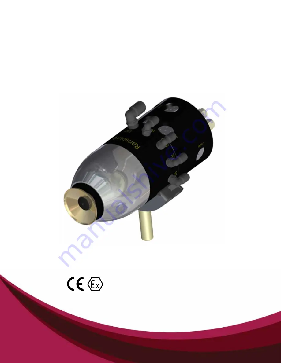
Ransburg

AEROBELL   268

TM

IMPORTANT:

  Before using this equipment, 

carefully read SAFETY PRECAUTIONS, starting 

on page 1, and all instructions in this manual.  

Keep this Service Manual for future reference.

Service Manual Price:           $50.00 (U.S.)

Содержание AEROBELL 268 A13657

Страница 1: ...vice Manual for future reference Service Manual Price 50 00 U S MODEL A13657 SERVICE MANUAL LN 9282 14 June 2014 Ransburg AEROBELL 268 TM IMPORTANT Before using this equipment carefullyreadSAFETYPRECAUTIONS starting on page 1 and all instructions in this manual Keep this Service Manual for future reference Service Manual Price 50 00 U S ...

Страница 2: ...ATION 25 26 AIR HEATER REQUIREMENTS 27 28 FLUID CONNECTIONS 28 HIGH VOLTAGE 29 INTERLOCKS 29 HIGH VOLTAGE CABLE ASSEMBLIES 30 HIGH VOLTAGE CABLE CONFIGURATIONS 30 AEROBELL 268 HIGH VOLTAGE CONNECT AT ATOMIZER END 30 AEROBELL 268 CASCADE CONNECTION 31 OPERATION 32 36 TURBINE SPEED 32 BEARING AIR 33 BRAKE AIR 33 ELECTROSTATIC VOLTAGE 33 SHAPING AIRS 34 FLUID FLOW RATE CONTROL 34 FLUID TIP STREAM AND...

Страница 3: ...5MM BELL CUP 52 68 PAGE CONTENTS Cont MAINTENANCE 37 68 PARTS IDENTIFICATION 69 83 MODEL IDENTIFICATION 69 71 APPLICATOR PARTS BREAKDOWN PARTS LIST 72 73 VALVE MANIFOLD PARTS LIST 74 SHAPE AIR KIT SELECTION 75 76 FIBER OPTIC CABLE LENGTH 77 HIGH VOLTAGE CABLE 77 HIGH VOLTAGE RESISTOR ASSEMBLY 78 EXTERNAL CASCADE COMPONENTS 78 ACCESSORIES LUBRICANTS 79 SERVICE KITS 80 RECOMMENDED SPARE PARTS 81 83 ...

Страница 4: ...such variations inevitable Compare this manual with your system installation drawings and appropriate Ransburg equipment manuals to reconcile such differences Careful study and continued use of this manual will provide a better understanding of the equipment and process resulting in more efficient operation longer trouble free service and faster easier troubleshooting Ifyoudonothavethemanualsand s...

Страница 5: ...point at minimum of 5 C 9 F greater than the ambient temperature It is the end users responsibility to insure this condition is met Spray booth ventilation must be kept at the rates required by NFPA 33 OSHA country and local codes In addition ventilation must be maintained during cleaning operations using flammable or combustible solvents Electrostatic arcing must be prevented Safe sparking distan...

Страница 6: ...eas free of flammable or combustible materials The current overload sensitivity if equipped MUST be set as described in the corresponding section of the equipment manual Protection against inadvertent arcing that is capable of causing fire or explosion is lost if the current overload sensitivity is not properly set Frequent power supply shutdown indicates a problem in the system which requires cor...

Страница 7: ...ot be worn Grounding straps on wrists or legs may be used to assure adequate ground contact Operators must not be wearing or carrying any ungrounded metal objects When using an electrostatic handgun operators must assure contact with the handle of the applicator via conductive gloves or gloves with the palm section cut out NOTE REFER TO NFPA 33 OR SPECIFIC COUNTRY SAFETY CODES REGARDING PROPER OPE...

Страница 8: ...roved for use in hazardous locations the power supply control cabinet and all other electrical equipment must be located outside Class I or II Division 1 and 2 hazardous areas in accordance with NFPA 33 and EN 50176 Turn the power supply OFF before working on the equipment Test only in areas free of flammable or combustible material Testing may require high voltage to be on but only as instructed ...

Страница 9: ...el in accordance with the manufacturer s documentation 8 The certification of this equipment relies upon the following materials used in its construction If the equipment is likely to come into contact with aggressivesubstances thenitistheresponsibility oftheusertotakesuitableprecautionsthatprevent itfrombeingadverselyaffected thusensuringthat the type of protection provided by the equipment is no...

Страница 10: ...acturers instructions The end user must insure that installation is in ac cordance with all applicable requirements of EN 50 176 This includes the means of fire protection and fire detection being installed with this system Before servicing bell insure that all voltage is com pletely de energized and the bell cup is not rotating Minimum1minutewaitafterturbineairhasbeenshutoff If ignitable fluids a...

Страница 11: ...625 00 028 0 7 STRAIGHT 01 A13625 01 035 0 9 STRAIGHT 02 A13625 02 039 1 0 STRAIGHT 03 A13625 03 043 1 1 STRAIGHT 04 A13625 04 047 1 2 STRAIGHT 05 A13625 05 062 1 6 STRAIGHT 06 A13625 06 093 2 4 STRAIGHT 07 A13625 07 125 3 2 STRAIGHT 09 A13625 08 010 0 25 STRAIGHT 10 A13645 00 028 0 7 INDUSTRIAL 11 A13645 01 035 0 9 INDUSTRIAL 12 A13645 02 039 1 0 INDUSTRIAL 13 A13645 03 043 1 1 INDUSTRIAL 14 A136...

Страница 12: ...65MM ALUMINUM PLATED A12782 00 A13644 00 01 A13676 00 65MM TITANIUM A13675 00 A13644 00 02 A12833 01 30MM ALUMINUM PLATED A12832 00 A13274 00 03 A12833 03 30MM TITANIUM A13531 00 A13274 00 00 A13032 01 DUAL FLEX SINGLE SHAPE AIR DIRECT CHARGE 01 A13032 02 MONO FLEX DUAL SHAPE AIR DIRECT CHARGE 02 A13032 03 30MM DUAL SHAPE AIR DIRECT CHARGE Aerobell 268 Atex FM LN 9282 14 9 ...

Страница 13: ...scription Part 0 A13691 00 8 VALVES 3 PAINT 3 DUMP 1 SOLVENT 1 AIR 1 A13691 01 6 VALVES PAINT 1 AND 2 DUMP 1 AND 2 AIR SOLVENT 2 A13691 02 4 VALVES PAINT 1 DUMP 1 AIR SOLVENT 0 NONE NONE 1 A13082 02 RPM 419 A12889 00 A11229 00 A12088 00 A11338 00 A11922 00 A10766 00 59972 00 Aerobell 268 Atex FM LN 9282 14 10 ...

Страница 14: ...Configuration Drawing 0 NO POWER SUPPLY 0 1 DOMESTIC 10 RACK 1 80120 511 2 EUROPE 10 RACK 1 80120 512 3 CHINA 10 RACK 1 80120 513 4 DOMESTIC BOX STYLE 1 80100 511 5 EUROPE BOX STYLE 1 80100 512 6 CHINA BOX STYLE 1 80100 513 Aerobell 268 Atex FM LN 9282 14 11 ...

Страница 15: ...ot exceed 100 MW Protective clothing including gloves shall comply with EN 1149 5 the measured insulation resistance shall not exceed 100 MW Part Dash Description TABLE H SPINDLE ASSEMBLY 0 NO CABLE 1 HIGH VOLTAGE CABLE 15 A13659 15 2 HIGH VOLTAGE CABLE 25 A13659 25 3 HIGH VOLTAGE CABLE 50 A13659 50 0 NONE NONE 1 SILVER SHAFT STYLE A12777 00 2 BLACK SHAFT STYLE A12777 02 Aerobell 268 Atex FM LN 92...

Страница 16: ...ble turbine assembly after the warranty period Machine mountable Non hollow wrist robot mountable 30mm dual shape air configuration for opti mum pattern control 65mm Mono Flex and Dual Flex shaping air configuration for optimum pattern control 30 and 65mm Bell cups are electroless nickel coated Aluminum and Titanium Figure 1 Aerobell 268 Proven long life air bearing spindle Speed control This unit...

Страница 17: ...mum Pressure 10 bar 150 psi Viscosity 20 to 40 Seconds Ford Cup 4 Viscosity 20 to 45 Seconds AFNOR Cup 4 Paint Resistivity 0 1 MW to Air Pressure Microvalve Pilot 4 9 bar Min 10 bar Max 75 150 psi Bearing Air 5 5 bar Min 7 bar Max 80 100 psi Shaping Air 7 bar Max 100 psi Brake Air 4 bar Min 7 bar Max 60 100 psi Change Time Rotary Atomizer Less than 5 minutes Bell Less than 5 minutes Distance Targe...

Страница 18: ...OPERATING CHARACTERISTICS AND SPECIFICATIONS Aerobell 268 Introduction LN 9282 14 15 ...

Страница 19: ...OPERATING CHARACTERISTICS AND SPECIFICATIONS Aerobell 268 Aerobell 268 Aerobell 268 Introduction LN 9282 14 16 ...

Страница 20: ...OPERATING CHARACTERISTICS AND SPECIFICATIONS Aerobell 268 Aerobell 268 Aerobell 268 Introduction LN 9282 14 17 ...

Страница 21: ...DIMENSIONAL CHARACTERISTICS Aerobell 268 Introduction LN 9282 14 18 ...

Страница 22: ...r are also the Turbine serial number IMPORTANT NUMBERS Turbine Serial Number Located On the Spindle Barrel Serial Number Located On Back Face Of Cup Bell Cup Part Number Located On Back face Of Cup AXXXXX Atomizer Serial Number Located on side of valve manifold Aerobell 268 Introduction LN 9282 14 19 ...

Страница 23: ...T DUMP 2 4MM 5 32 O D TUBE 10 PD3 PAINT DUMP 3 4MM 5 32 O D TUBE 11 PTS SOLVENT TRIGGER 4MM 5 32 O D TUBE 12 PTI PAINT TRIGGER 2 4MM 5 32 O D TUBE 13 PDI PAINT DUMP 1 4MM 5 32 O D TUBE 14 PTA AIR TRIGGER 4MM 5 32 O D TUBE 15 CUP WASH 4MM 5 32 O D TUBE 16 PAINT 2 PAINT SUPPLY 2 8MM 5 16 O D TUBE 17 PAINT 3 PAINT SUPPLY 3 8MM 5 16 O D TUBE 18 DUMP 2 DUMP OUTLET 2 8MM 5 16 O D TUBE 19 DUMP 3 DUMP OUT...

Страница 24: ...COLOR CONFIGURATION The valve manifold can be ordered in the configurations below See top as sembly order matrix In the case that a valve pocket is not required a plug kit 77620 00 is available to block off the valve seat and valve cavity Aerobell 268 Introduction LN 9282 14 21 ...

Страница 25: ...re filter should be brass stainless steel aluminum or hose poly nylon nyliner etc 6 Do not use PTFE tape pipe dope or other threadsealantdownstreamofthebearingairfilter Loose flakes of PTFE tape or other sealant can break loose and plug the very fine air holes in the turbine bearings 7 Use clear see through air tubing between the bearing air filter and bearing air fitting to clearly indicate to th...

Страница 26: ...never be replaced with Nylon hoses Only Polyamide Nylon hoses can be used for air connections Polyure thane hoses are prohibited PFA Ultra Pure Polytetrafluoroethylene Any user supplied air hoses must be rat ed at a minimum working pressure of 100 psig 7 bar C A U T I O N Any user supplied fluid hoses must be rated at a minimum working pressure of 150 psig 10 bar C A U T I O N Aerobell 268 Install...

Страница 27: ...pe filters musts be used in an Aerobell 268 system The filter elements must be re placed regular schedule to assure clean air It is the user s responsibility to ensure clean air at all times Turbine failure result ing form contaminated air will not be cov ered under warranty If other filters are incor porated in the system the filters to be used must have filtering capacities equal or better than ...

Страница 28: ... EARTH GROUND 5 BOOTH WALL HAZARDOUS AREA SIDE 6 BOOTH WALL SAFE AREA SIDE 7 OPTIONAL FIBER OPTIC 8 VERTICAL GUN BAR OR RECIPROCATOR OR STATIONARY STAND 9 AB 268 APPLICATOR Item Description TYPICAL MULTIPLE APPLICATOR CONFIGURATION Typical Multiple Applicator Configuration Aerobell 268 Installation LN 9282 14 25 7 7 7 7 9 9 9 9 ...

Страница 29: ...Aerobell 268 Installation LN 9282 14 26 ...

Страница 30: ...hus it is recommendedthatairheatersbeinstalledintothe atomizer air supply lines i e Turbine air The air heaters must be of sufficient capacity capable of raising the incoming air temperature at least 40 F 4 4 C at a flow rate of 60 SCFM per applicator The actual air heater process setting depends on applicator fluid flow rate load booth conditions turbineairflowsettings andincomingairtempera ture ...

Страница 31: ...material used is heated check the maximum rated temperature for the fluid tubing used Polyethylene tubing H 2338 and H 2339 is rated for a maximum of 80 F 27 C Nylon tubing H 2340 and H 2341 is rated for 200 F 95 C maximum W A R N I N G Arcing fire hazard exist if ungrounded metal connections air or fluid are used in the spray area Use plastic non conductive connections or ensure metal connections...

Страница 32: ... down for about two minutes Provisions should be made to assure that the operator waits at least three minutes after shutting off the turbine air and before shutting off the main air supply Under normal operation the high volt age and or coating material must never be turned on unless the bell cup is mounted on the motor shaft and the turbine is rotating Pneumatic input to the turbine air inlet mu...

Страница 33: ...connectors HIGH VOLTAGE CABLE CONFIGURATIONS A13659 XX is a resin core conductor cable with a polyethylene jacket and an exterior Nylon sleeve It comes pre assembled with banana jacks at each end 4 Ensure that no conductive sponges are used in any connector 5 A13659 XX cables are not to be modified in the field To do so will void any and all warranties that may exist Do not use any di electric gre...

Страница 34: ...ot need to connect any fittings to return bearing air back to the controller If using a controller for speed use the fittings pro vided to send an air signal back to the controller These fittings must be non metalic Reference minimum bearing air pressure at the applicator is 80 psi 5 5 bars AEROBELL 268 BEARING AIR FEEDBACK Aerobell 268 Installation LN 9282 14 31 ...

Страница 35: ...ation of electrostatic equipment Oper ators must read all instructions and safety precautions prior to using this equipment see NFPA 33 EN 50 176 Electrical discharge on a high electrical capacitance fluid paint system can cause fire or explosion with some materials If arcing occurs when a specific material is used turn the system OFF and verify that the fluid is non flammable In these conditions ...

Страница 36: ...main line air Bearing damage and subsequent tur bine failure caused by running the turbine without bearing air will not be covered under Ransburg warranty When turning the turbine on bearing air must be present Likewise bearing air must remain on when the turbine air is turned off until the turbine stops spinning Never turn off bearing air to cause the turbine to stop spinning Brake air can be use...

Страница 37: ...nputs on the atomizer body will be required to be plugged Either input can be used for Mono Flex SAI or SAO Dual Flex ShapingAir Configuration Both inputs are required Pattern adjustment Increasing the inner air will make the pattern smaller Increasing the outer air will make the pattern larger As the picture on the right shows the fluid stream should be straight and steady It is best to start out...

Страница 38: ...acting the applicator bell cup when the applicator is energized or op erating Fluid Flow Rate Check In the test mode the flow rate can be measured byremovingthebellcupfromtheatomizer turning the fluid flow on and capturing the material in a graduated beaker or measuring cup for a fixed period of time shaping air high voltage and turbine air must be off TARGET DISTANCE The distance from the Aerobel...

Страница 39: ...parts under high volt age are discharged to an energy of less than 0 24mJ before these parts may be serviced Appropriate measures shall ensure that the resistance to earth of the sus pending point of the work piece shall not exceed 1MW measured at 500v or 1000v Use only electrically conductive con tainer for cleaning liquids the containers must be earthed to ground TURBINE EXHAUST Turbine air must...

Страница 40: ...ers responsibility to insure this condi tions is met Never remove Aerobell 268 while it is under pressure If ignitable fluids are used for cleaning purposes all parts must completely dis charged of high voltage W A R N I N G Electrical shock arcing and fire hazards can exist during maintenance The high volt age must be turned off before entering the spray area and performing any maintenance proced...

Страница 41: ...with flushing However if there is any remaining paint build up on any areas of the bell after flushing the bell should be removed for hand cleaning 4 Clean the bell cup by soaking in an appropriate solvent as long as necessary to loosen paint Use a soft bristle brush dipped in solvent to remove paint Make sure all signs of paint are removed See the following Warning Rinse and dry bell Using a non ...

Страница 42: ...dump valve if equipped flushing all paint from the supply lines and valve module Open the solvent valve if equipped flushing all paint from the fluid tube and through the at omizer bell assembly Verify that high voltage is OFF turbine drive air is OFF and that the bell cup has stopped spinning The bearing air and shaping air should remain ON Clean all external surfaces of the applica tor using a l...

Страница 43: ...to hand wipe Turbine drive air must be off but leave bearing air on The shaping air should have approximately 70 SLPM air flow through each to prevent the solvent from entering these passages Do not spray the unit with a solvent applica tor used for cleaning The cleaning fluid under pressure may aid conductive materials to work into hard to clean areas or may allow fluids to be forced into the tur...

Страница 44: ...en as necessary Replace elements at least every 4 6 months or more often W A R N I N G To reduce the risk of fire or explosion Solvents used for cleaning must have a flash point at minimum of 5 C 9 F greater than the ambient temperature It is the end users responsibility to insure this condi tion is met Since electrostatic equipment is involved these solvents should also be non polar Example of no...

Страница 45: ...erial Never use any kind of pick instrument to clean these holes as it will damage them 6 Soaking the bell in solvent may aid in loosening or removing paint build up It is recommended that the splash plate be removed and cleaned separately 7 Use a soft bristle brush dipped in solvent to remove paint build up from the serration cuts paint feed holes or slots and external and internal surfaces of th...

Страница 46: ... holes for blockage Blow holes clear with compressed air after some time of soaking in solvent DO NOT use any type of pick to clear the holes Damage may result to parts and could affect performance of the equipment If holes are damaged oversized holes blockage gouges it must be replaced Inspect Bell Cup Daily Check for signs of damage such as nicks heavy scratches dents or excessive wear Replace t...

Страница 47: ...Tightening Fluid tip inspection cleaning Inspect Valve and Seat Assembly for leaking Replace Valves and or Seats in valve module Verify Resistance of High Voltage Resistor High Voltage Cable Inspections High Voltage Testing Inspect all screws Replace if broken Inspect for wear Tighten per specifications Inspect Turbine Spindle Taper and Threads Replace Bell Cups Replace Splash Plates Inspect and C...

Страница 48: ...8 Tool Kit A13082 XX A11229 00 Fluid Tip Tube Removal Tool RPM 419 Bell Cup Combo Wrench Adjustable Wrench Not Supplied in Tool Kit 59972 00 Dielectric Grease Not Supplied in Tool Kit A12899 00 Bell Cup Removal Tool A12088 00 Turbine Retaining Ring Wrench Aerobell 268 Maintenance LN 9282 14 45 ...

Страница 49: ...l Tool A10766 00 Microvalve Seat Removal Tool A11388 00 Splash Plate Removal Tool 6mm Hex Key Wrench NOT supplied with the tool kit 6mm Ball End Hex Key Driver NOT supplied with the tool kit 17mm Open End Wrench NOT supplied with the tool kit A11373 00 Tubing Removal Tool NOT supplied with the tool kit Aerobell 268 Maintenance LN 9282 14 46 ...

Страница 50: ...pair entire assembly is 60 Minutes NOTE Step 1 Place the Aerobell 268 on a clean sta ble working surface or mount Remove the Shaping Air Shroud by hand no tool required Step 2 Locate the Cup Wash Fitting that is mounted on the Shape Air Ring Aerobell 268 Maintenance LN 9282 14 47 ...

Страница 51: ...ble click is heard Note Be careful not to drop the Cup Wash Ferrule Make sure when assembling the Cup Wash Fitting that the ferrule taper end is inserted into the Cup Wash Fitting Remove Shape Air Ring Pull straight off Note The Shape Air Ring is sealed with a O ring and may be difficult to remove Note When reassembling an au dible Click should be heard Aerobell 268 Maintenance LN 9282 14 48 ...

Страница 52: ... have to be in line when assembling Note Two 2 locating pins are mounted on the back of the Shape Air Ring to insure proper alignment Insert the Bell Cup Combo Wrench RPM 419 across the flats located on the Turbine Remove the Bell Cup by hand Bell Cup When reassembling the Bell Cup hand tighten is sufficient Yellow Dot Yellow Line Blue Line DISASSEMBLY PROCEDURES 30mm Bell Cup and Shape Air Ring A...

Страница 53: ...s pressed into the Bell Cup Insert the narrow end of the Splash Plate Removal Tool A11388 00 into the hole on the back side of the Bell Cup Usingahardthrustfromthepalm ofyourhand removetheSplashPlate DISASSEMBLY PROCEDURES 30mm Bell Cup and Shape Air Ring Aerobell 268 Maintenance LN 9282 14 50 ...

Страница 54: ... Plate A11388 00 Splash Plate Removal Tool To reassemble the Splash Plate place the Bell Cup with the back down on a flat surface and insert the Splash Plate into the Bell Cup hole Using the large end of A11388 00 Splash Plate RemovalToolgentlypushintoposition Until an audible click is heard Step 13A Verify depth of insert to dimension range shown Aerobell 268 Maintenance LN 9282 14 51 ...

Страница 55: ...ISASSEMBLY PROCEDURES 65mm Bell Cup and Shape Air Ring Place the Aerobell 268 on a clean stable working surface or mount Remove the ShapingAir Shroud by hand no tool required Locate the Cup Wash Fitting that is mounted on the Shape Air Ring Aerobell 268 Maintenance LN 9282 14 52 ...

Страница 56: ...ith fingers until an audible click is heard Note Be careful not to drop the Cup Wash Ferrule Make sure when assembling the Cup Wash Fitting that the ferrule taper end is inserted into the Cup Wash Fitting Insert the Bell Cup Removal Tool A12899 in the hole located on the Shape Air Ring and align with the hole in the Turbine Shaft Aerobell 268 Maintenance LN 9282 14 53 ...

Страница 57: ...g is sealed with a O ring and may be difficult to remove Note When reassembling an audible Click should be heard Note The Shape Air Ring has a blue alignment mark The blue alignment mark will line up with the yellow dot located on the Atomizer Body and the small yellow line lo cated on the Turbine All three 3 alignment marks will have to be in line when assembling Yellow Dot Yellow Line Blue Line ...

Страница 58: ... of the Shape Air Ring to insure proper alignment Locate the Splash Plate that is pressed into the Bell Cup Insert the narrow end of the Splash Plate Removal Tool A11388 00 into the hole on the back side of the Bell Cup Using a hard thrust from the palm of your hand remove the Splash Plate Aerobell 268 Maintenance LN 9282 14 55 ...

Страница 59: ...eassemble the Splash Plate place the Bell Cup with the back down on a flat surface and insert the Splash Plate into the Bell Cup hole Using the large endofA11388 00SplashPlateRemoval Tool gently push into position Until an audible click is heard Step 13A Verify depth of insert to dimension range shown Aerobell 268 Maintenance LN 9282 14 56 ...

Страница 60: ...embled Note There is an O ring behind the Fluid Tip Take care not to lose Using the Turbine Retaining Ring Tool A12088 00 remove the Tur bine Retaining Ring Step 14 Remove the Fluid Tip using the A11229 00 Fluid Tip Tube Removal Tool The Threads on the Fluid Tips are LEFT HANDED NOTE Aerobell 268 Maintenance LN 9282 14 57 ...

Страница 61: ...he Turbine no tool required Pull straight off Note the alignment marks The Turbine sealed with a O ring and may be difficult to remove NOTE Step 17 Note the alignment marks on the Atomizer Body and Turbine Retaining Ring Yellow Dot Yellow Line Aerobell 268 Maintenance LN 9282 14 58 ...

Страница 62: ...ing the opposite end of the Fluid Tip Tube Removal Tool A11229 00 When re installing tighten to 65 75 In Lbs 7 64 8 42 N m Step 20 Note Two 2 locating pins are mount ed on the back of the Turbine to insure proper alignment When assembling these pins will easily insert when the alignment marks are properly matched Aerobell 268 Maintenance LN 9282 14 59 ...

Страница 63: ... high voltage cable end or in atom izer body Insert pins of tool into valve cap and remove counter clockwise Step 23 Remove high voltage cable DISASSEMBLY PROCEDURES 65mm Bell Cup and Shape Air Ring Aerobell 268 Maintenance LN 9282 14 60 ...

Страница 64: ...6 Remove valve seat by turning counter clockwise Pull microvalve out inspect o rings for damage Replace valve SEAT with new part DISASSEMBLY PROCEDURES 65mm Bell Cup and Shape Air Ring Aerobell 268 Maintenance LN 9282 14 61 ...

Страница 65: ...s in 1 69 2 6 Nm Apply A11544 00 petroleum jelly to o rings before installing microvalve Torque to 15 20 lbs in 1 69 2 6 Nm after valve is down Loosen nut on fiber optic fitting DISASSEMBLY PROCEDURES 65mm Bell Cup and Shape Air Ring Aerobell 268 Maintenance LN 9282 14 62 ...

Страница 66: ...d can be removed from atomizer body or remove en tire fiber optic tube Remove 3 M8 SHCS from valve manifold Use a ball type hex driver 6mm for the screws as shown Tighten to 5 10 lbs in 56 1 13 Nm torque DISASSEMBLY PROCEDURES 65mm Bell Cup and Shape Air Ring Aerobell 268 Maintenance LN 9282 14 63 ...

Страница 67: ...Step 37 Step 36 Step 35 Remove screw 1 Remove screw 2 Remove screw 3 DISASSEMBLY PROCEDURES 65mm Bell Cup and Shape Air Ring Aerobell 268 Maintenance LN 9282 14 64 ...

Страница 68: ...loosening fitting Install fitting tight until an audible clicking is heard or felt Note the direction of ferrule when re installing Slide the valve body assembly away from the atomizer body DISASSEMBLY PROCEDURES 65mm Bell Cup and Shape Air Ring Aerobell 268 Maintenance LN 9282 14 65 ...

Страница 69: ...d insert pull straight out Inspect o ring if leak is observed oth erwise do not disturb o ring Assemble cup wash tubing as per steps 39 and 40 DISASSEMBLY PROCEDURES 65mm Bell Cup and Shape Air Ring Aerobell 268 Maintenance LN 9282 14 66 ...

Страница 70: ... to 5 lbs in 56 Nm torque To remove fiber optic tube assembly use the 17mm hex on the tube and turn counter clockwise Unscrew fiber optic sen sor from tube Re install by hand until tight DISASSEMBLY PROCEDURES 65mm Bell Cup and Shape Air Ring Aerobell 268 Maintenance LN 9282 14 67 ...

Страница 71: ...Step 47 Verify dimension before installing into atomizer body DISASSEMBLY PROCEDURES 65mm Bell Cup and Shape Air Ring 1 676 1 658 42 57 42 113 Aerobell 268 Maintenance LN 9282 14 68 ...

Страница 72: ...13625 01 035 0 9 STRAIGHT 02 A13625 02 039 1 0 STRAIGHT 03 A13625 03 043 1 1 STRAIGHT 04 A13625 04 047 1 2 STRAIGHT 05 A13625 05 062 1 6 STRAIGHT 06 A13625 06 093 2 4 STRAIGHT 07 A13625 07 125 3 2 STRAIGHT 08 A13625 08 010 0 25 STRAIGHT 09 A13645 00 028 0 7 INDUSTRIAL 10 A13645 01 035 0 9 INDUSTRIAL 11 A13645 02 039 1 0 INDUSTRIAL 12 A13645 03 043 1 1 INDUSTRIAL 13 A13645 04 047 1 2 INDUSTRIAL 14 ...

Страница 73: ...30MM TITANIUM A13531 00 A13274 00 00 A13032 01 DUAL FLEX DIRECT CHARGE 65MM 01 A13032 02 MONO FLEX DIRECT CHARGE 65MM 02 A13032 03 30MMM DIRECT CHARGE 0 A13691 00 8 VALVES 3 PAINT 3 DUMP 1 SOLVENT 1 AIR 1 A13691 01 6 VALVES PAINT 1 AND 2 DUMP 1 AND 2 AIR SOLVENT 2 A13691 02 4 VALVES PAINT 1 DUMP 1 AIR SOLVENT 0 NONE 0 NONE 1 A13082 02 1 RPM 419 A12899 00 A11229 00 A12088 00 A11338 00 A11922 00 A10...

Страница 74: ...ion TABLE H SPINDLE ASSEMBLY 0 NO CABLE 1 A13659 15 HIGH VOLTAGE CABLE 15 FT 2 A13659 25 HIGH VOLTAGE CABLE 25 FT 3 A13659 50 HIGH VOLTAGE CABLE 50 FT 0 NONE NONE 1 A12777 00 SILVER SHAFT STYLE 2 A12777 02 BLACK SHAFT STYLE Aerobell 268 Parts Identification LN 9282 14 71 ...

Страница 75: ...Aerobell 268 Assembly Aerobell 268 Parts Identification LN 9282 14 72 ...

Страница 76: ... A11226 00 RETAINER FLUID TUBE 19 1 79001 42 O RING SOLVENT PROOF 20 1 J SPINDLE ASSEMBLY 21 1 79001 11 O RING SOLVENT PROOF 22 1 A12781 00 TURBINE RETAINING RING 23 1 B BELL CUP ASSEMBLY 24 1 C SHAPING AIR KIT 31 10 A11252 01 TUBING FEP 32 5 A13664 00 FITTING 8MM 33 1 A13665 00 FITTING 12MM 34 1 A13668 00 POST MOUNT ASSEMBLY 35 1 D VALVE MANIFOLD ASSEMBLY 36 1 A13692 00 FIBER OPTIC SENSOR ASSEMBL...

Страница 77: ...ALLATION 1 5 APPLY A11545 00 PETROLATUM JELL TO ALL O RINGS BEFORE ASSEMBLING 1 1 A VALVE MANIFOLD 2 B 78949 00 VALVE ASSEMBLY 3 B 77367 00 VALVE SEAT ASSEMBLY 4 B LSFI0022 05 FITTING 5 B 77516 04 COLLET 4 MM 6 B 79001 30 O RING SOLVENT PROOF 7 1 79001 23 O RING SOLVENT PROOF A13691 00 A13653 00 8 ALL VALVES A13691 01 A13653 01 6 PAINT 1 PAINT 2 DUMP 1 DUMP 2 AIR SOLVENT A13691 02 A13653 02 4 PAIN...

Страница 78: ...A13032 02 MONO FLEX DIRECT CHG Aerobell 268 Parts Identification LN 9282 14 75 ...

Страница 79: ...SELECTION B SHAP AIR MANIFOLD C SHROUD D E F Item Part Description Qty 1 A SHAPE AIR RING 1 2 B SHAPE AIR MANIFOLD 1 3 C SHROUD 1 4 79001 10 O RING SOLVENT PROOF D 5 79001 52 O RING SOLVENT PROOF E 6 A12898 00 SHAPE AIR PLUG 1 7 79001 16 O RING SOLVENT PROOF 1 8 7554 72 O RING 1 9 79001 11 O RING SOLVENT PROOF F 10 79001 35 O RING SOLVENT PROOF G A13032 03 30MM SHAPE AIR A13032 03 30mm Direct Char...

Страница 80: ...0 Ft 12 2m Long Fiber Optic Cable A12409 07 50 Ft 15 2m Long Fiber Optic Cable A12409 08 65 Ft 19 8m Long Fiber Optic Cable A12409 08 75 Ft 22 9m Long Fiber Optic Cable A12409 10 100 Ft 30 5m Long Fiber Optic Cable Part Description FIBER OPTIC CABLE LENGTH Dash Description TABLE G HIGH VOLTAGE CABLE 0 NO CABLE 1 HIGH VOLTAGE CABLE 15 A13659 15 2 HIGH VOLTAGE CABLE 25 A13659 25 3 HIGH VOLTAGE CABLE...

Страница 81: ...IN 4 8521 06F SET SCREW 5 80104 01 ASSEMBLY EXTERNAL 6 79350 01 ASSEMBLY CASCADE Item 80104 01 EXTERNAL CASCADE COMPONENTS Part Description Not included with the 80104 01 Assembly but with the A13386 XX Assembly Consult Power Supply Manual CP 13 02 or CP 13 05 for available parts for the power supplies Aerobell 268 Parts Identification LN 9282 14 78 ...

Страница 82: ...0 and Test Lead Assy 76664 00 76652 03 Kit for measuring paint resistivity Includes Multi Function Meter 76634 00 and Paint Probe Assy 7922 00 76652 04 Deluxe Kit performs all functions listed above Includes Multi Function Meter 76634 00 Paint Probe Assy 7922 00 Test Lead Assy 76664 00 and High Voltage Probe Assy 76667 00 A11545 00 Petrolatum Jell Lubricant for all O Rings Part Description ACCESSO...

Страница 83: ... OD to 6mm OD Tube A11570 04 Reducing Straight Connector Push to Connect 10mm OD to 4mm OD Tube A11570 05 Reducing Straight Connector Push to Connect 10mm OD to 6mm OD Tube A11570 06 Reducing Straight Connector Push to Connect 10mm OD to 8mm OD Tube A11570 07 Reducing Straight Connector Push to Connect 12mm OD to 8mm OD Tube A11570 08 Reducing Straight Connector Push to Connect 12mm OD to 10mm OD ...

Страница 84: ... 00 SCREW M10 X 16MM LONG 2 4 A12821 00 CUP WASH FITTING 1 2 A12822 00 CUP WASH FERRULE 3 6 A13382 00 RESISTOR ASSEMBLY 1 A13656 00 INSERT 1 A13661 00 SCREW M5 X 20 NYLON 2 4 A13664 00 FITTING 8MM 1 2 A13665 00 FITTING 12MM 1 2 A13692 00 FIBER OPTIC SENSOR ASSEMBLY 1 78949 00 VALVE ASSEMBLY 1 2 77367 00 VALVE SEAT ASSEMBLY 1 2 LSFI0022 05 FITTING 2 4 Select Option Below Bell Cup Assembly W Splash ...

Страница 85: ...0 9mm Industrial 1 A13645 02 039 1 0mm Industrial 1 A13645 03 043 1 1mm Industrial 1 A13645 04 047 1 2mm Industrial 1 A13645 05 062 1 6mm Industrial 1 A13645 06 093 2 4mm Industrial 1 A13645 07 125 3 2mm Industrial 1 A13645 08 010 0 25mm Industrial 1 Select Option Below Shaping Air Kit A13032 01 Dual Flex 65mm A12909 00 Outer Shroud 65mm 1 A12911 00 Shaping Air Ring 65mm 1 A12910 00 Shape Air Mani...

Страница 86: ...01 16 O ring 1 7554 72 O ring 1 A12898 00 Shape Air Plug 1 Select Option Below Shaping Air Kit A13032 03 30mm A12830 00 Outer Shroud 30mm 1 A12831 00 Shape Air Manifold 30mm 1 79001 52 O ring 1 79001 10 O ring 1 79001 16 O ring 1 7554 72 O ring 1 A12898 00 Shape Air Plug 1 Aerobell 268 Parts Identification LN 9282 14 83 ...

Страница 87: ...rge energy must be less than 300 mJ prior to reaching the parts Use non flamable cleaning agents if possible Those used for equipment flushing should have flash points equal to or higher than those of the coating material Those solvents used for cleaning must have a flash point at minimum of 5 C 9 F greater than the am bient temperature It is the end users responsibility to insure this condition i...

Страница 88: ...ding to 5 7 1 cannot be achieved the possible discharge energy shall not exceed 0 24mJ The resistance to earth from the suspending point of each workpiece shall not exceed 1 MΩ The voltage during measurement shall be 500 V or 1000 V The construction of hangers shall ensure that the work pieces remain earthed during the coating process Note Since workpieces are often earthed by metallic hooks it is...

Страница 89: ...l be cut off automatically EN 13478 shall be observed It shall be checked in each individual case whether a present room protection system is also able to fulfill the function of a locally acting automatic fire extin guishing system Where conductive parts are used for the coating material supply system these parts shall be either bonded to earth or connected with the high voltage supply system so ...

Страница 90: ...CATOR ASSOCIATEDVALVESAND TUBING AND SUPPORTING HARDWARE IN PLASTIC SHRINK WRAP OR ANY OTHER NON APPROVEDCOVERING WILLVOIDTHIS WARRANTY RANSBURG S ONLY OBLIGATION UNDER THIS WARRANTY IS TO REPLACE PARTS THAT HAVE FAILED BECAUSE OF FAULTY WORKMANSHIPORMATERIALS THEREARE NOIMPLIEDWARRANTIESNORWARRANTIES OF EITHER MERCHANTABILITY OR FITNESS FOR A PARTICULAR PURPOSE RANSBURG ASSUMES NO LIABILITY FOR I...

Страница 91: ...Spare Parts Manufacturing 1910 North Wayne Street Angola Indiana 46703 9100 Telephone 260 665 8800 Fax 260 665 8516 Technical Service Assistance 320 Phillips Ave Toledo Ohio 43612 1493 Telephone toll free 800 233 3366 Fax 419 470 2233 2014 Finishing Brands Inc All rights reserved Models and specifications subject to change without notice ...

Отзывы: