


Troubleshooting RAD Devices
If a RAD is functioning properly and communicating with the HAL, all four of its LED status indicators
(Power, Comm, Audio Rx, and Audio Tx) will be green. The following table details possible causes and
solutions if one or more of these indicators are off or red. If you detect a problem with a RAD, we rec-
ommend first checking the HAL to determine if the problem is originating there.
NOTE
:
It is best to check these indicators in the following order: Power, Comm, Audio Rx, and
Audio Tx. If the power isn’t working, nothing else will work. If the data communications (Comm)
isn’t working, Audio Tx will not work. If Audio Tx isn’t working, Audio Rx will not work.
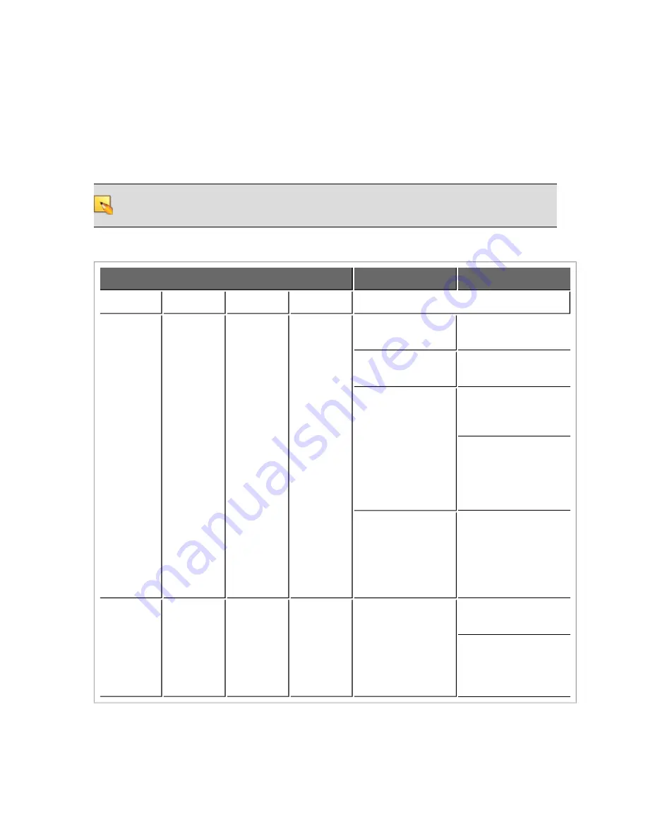
RAD Status Indicators
Possible Causes
Suggested Action
Power
Comm
Audio Tx
Audio Rx
OFF
OFF
OFF
OFF
Room is dark and
LEDs are off.
Shine a light on the
RAD front panel.
The HAL is not pow-
ered.
Power on the HAL.
A miswired or
broken cable is dis-
rupting power to the
RAD.
Use a cable tester to
verify CAT 5 ter-
mination.
If using a punch block,
verify that the brown
pair is properly
punched. (Assuming
T568B termination).
The cable is not
plugged into a HAL.
Plugging the RAD
cable into some other
device (like an Eth-
ernet switch) will not
supply power to the
RAD.
RED
GREEN
or
RED
GREEN
or
RED
GREEN
or
RED
There is excessive
voltage drop
between the HAL
and RAD.
Verify it is 24 AWG
(or heavier) cable.
Verify the cable length
from HAL to RAD has
not exceeded 150
meters.
CHAPTER 5: Troubleshooting Your HAL System Installation
51


